
Magnetic Coupling Types and Selection: Classification by Topography
When you are designing a sealless pump or a sealed fluid system, choosing the right magnetic coupling geometry is your very first step. If you get the topography wrong, you risk losing torque, wasting space, or driving up manufacturing costs. We break down the three primary geometric configurations we engineer to help you find the exact fit for your application.
Coaxial Magnetic Couplers
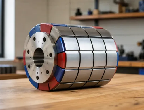
Also known as radial magnetic couplings, coaxial magnetic couplers consist of an inner rotor nested inside an outer rotor. The magnetic forces interact radially across a cylindrical air gap.
-
- Best For: High-pressure isolation walls and sealless pump torque transmission.
- Key Advantage: Excellent axial balance. Because the magnetic forces are balanced radially, it puts very little axial load on your motor bearings.
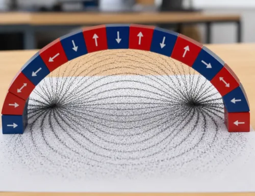
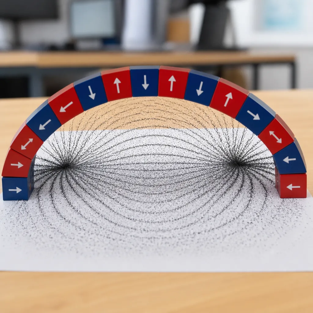
- Torque Optimization: We often leverage a Halbach array configuration in our coaxial builds to focus the magnetic field, maximizing torque density optimization without adding bulk.
Axial Disc Magnetic Couplings
Axial or disc magnetic couplings feature two face-to-face discs lined with alternating magnetic poles. The magnetic flux travels parallel to the shaft axis across a flat air gap.
-
- Best For: Tight spaces where axial length is limited but radial space is open.
- Key Advantage: Unmatched ease of installation. You can easily adjust the air gap dynamics just by shifting the axial distance between the two discs to fine-tune your torque slip points.
- The Tradeoff: They generate significant axial pull forces. Your system must be designed with robust bearings to handle the constant attraction force between the two plates.
Linear Magnetic Couplings
When your application requires straight-line automation instead of rotation, linear magnetic couplings are the go-to solution. They convert rotary actuator movements into pure linear force through a solid containment wall.
-
- Best For: Rodless cylinders, liquid handling automation, and cleanroom positioning tracks.
- Key Advantage: Complete mechanical isolation for back-and-forth movements, entirely eliminating the need for dynamic piston seals that wear out over time.
| Coupling Type | Primary Force Direction | Best Space Profile | Main Industrial Application |
|---|---|---|---|
| Coaxial / Radial | Radiální | Long / Narrow | Sealless Pumps & Mixers |
| Axial / Disc | Axiální | Short / Wide | Fan Drives & Flat Bulkheads |
| Lineární | Linear Axial | Long / Straight | Cleanroom Automation & Actuators |
Classification by Operating Physics: Functional Topologies
When we design permanent magnet couplings, look closely at how the magnetic fields interact across the air gap. The operating physics dictate exactly how torque transfers from the driving side to the driven side. Depending on your application speed, thermal limits, and slip requirements, we generally break these functional topologies down into three primary categories.
Synchronous Permanent Magnet Couplings
This is the most common topology we produce for high-efficiency power transmission. In synchronous magnetic couplings, both the inner and outer rotors lock into a fixed angular position. They rotate at the exact same speed ($1:1$ ratio) without any slip under normal operating conditions.
-
- Torque Transmission: Utilizes direct attraction and repulsion between opposing permanent magnet poles.
- Key Advantage: Zero mechanical slip means maximum efficiency and zero operational power loss during standard rotation.
- Overload Protection: If the system exceeds the maximum design limit—known as the pull-out torque calculation threshold—the rotors safely uncouple and slip to prevent catastrophic mechanical failure.
Because these systems rely on locked magnetic alignment, sudden stalls or severe thermal spikes can risk demagnetization. If you are dealing with extreme heat or locked-rotor scenarios, understanding the cause of demagnetization in permanent magnet motors and couplings is critical to keeping your drivetrain protected.
Eddy Current / Asynchronous Couplings
Unlike synchronous designs, eddy current couplings require relative motion (slip) between the driving and driven components to transmit torque. One side features permanent magnets, while the opposing side utilizes a high-conductivity copper or aluminum conductor rotor.
-
- Jak to funguje: As the magnetic rotor rotates past the conductor, it induces localized electrical currents called eddy currents. These currents generate their own opposing magnetic field, creating torque across the gap.
- Speed Control: Torque is directly proportional to the slip speed. This allows for soft starts and variable speed adjustments.
- Thermal Consideration: The primary trade-off here is eddy current power loss, which manifests as heat within the conductor plate and must be managed via passive or forced cooling.
Hysteresis Couplings
Hysteresis topologies provide a completely synchronous torque transmission up to a specific predefined limit, after which they offer smooth, continuous slipping without the massive heat spikes or wear found in other asynchronous systems.
| Vlastnost | Hysteresis Coupling | Eddy Current Coupling | Synchronous Coupling |
|---|---|---|---|
| Material Pair | Permanent Magnet + Hysteresis Material | Permanent Magnet + Conductor (Copper/Al) | Permanent Magnet + Permanent Magnet |
| Slip Behavior | Smooth, constant torque during slip | Torque increases with slip speed | Cannot slip without uncoupling |
| Main Use Case | Tension control & capping | Variable speed drives & soft starts | Sealless pump torque transmission |
By using a high-coercivity hysteresis alloy opposing the permanent magnets, these assemblies maintain a constant torque profile regardless of the relative slip speed. This makes them the premier choice for precise tensioning systems, bottling capping lines, and overload clutches.
Material Selection: The Foundation of Coupling Performance
When engineering high-performance magnetic couplings, selecting the right magnetic alloy dictates the entire system’s torque density and environmental limits. The choice between different rare-earth materials alters how a coupling performs under thermal stress and corrosive environments.
Sintered Neodymium (NdFeB) vs. Samarium Cobalt (SmCo)
For the majority of permanent magnet couplings, the decision comes down to Sintered Neodymium (NdFeB) or Samarium Cobalt (SmCo). Each material brings distinct mechanical and magnetic advantages to industrial operations:
-
- Sintered Neodymium (NdFeB): This alloy delivers the highest maximum energy product, allowing for extreme torque density optimization in compact spaces. It is the go-to choice for high-torque transmission at ambient temperatures. However, NdFeB is prone to high-temperature magnetic degradation and requires specialized coatings to prevent corrosion.
- Samarium Kobalt (SmCo): While it offers slightly lower raw magnetic strength at room temperature, SmCo features exceptional thermal stability and a high Curie temperature. For a deeper breakdown of these two powerhouses, we analyze how samarium-kobaltové vs. neodymiové magnety stack up across specific industrial environments. SmCo resists demagnetization and handles aggressive chemical exposure without needing protective plating.
| Magnetic Property | Sinterované NdFeB | Samarium Kobalt (SmCo) |
|---|---|---|
| Maximální provozní teplota | Up to 80°C – 230°C (Grade dependent) | Up to 250°C – 350°C |
| Torque Density | Ultra-High | Vysoká |
| Odolnost proti korozi | Poor (Requires coating) | Excellent (Uncoated) |
| Temperature Coefficient | Higher loss per °C | Exceptionally stable |
Secondary Industrial Magnet Alloys
While rare-earth elements dominate synchronous magnetic couplings, specific legacy applications utilize secondary alloys. Alnico magnets provide excellent temperature stability up to 520°C but feature low coercive force, making them highly susceptible to demagnetization under reverse torque loads. Ferrit (keramický) magnets offer a low-cost, corrosion-resistant alternative, though their low energy product drastically limits torque delivery, restricting them to low-load, cost-sensitive applications.
NBAEM’s Material Advantage
At NBAEM, we remove the guesswork from custom magnetic assembly design. We source and process premium-grade raw materials to match your exact application parameters. Whether your system demands a complex Halbach array configuration to maximize flux density or ultra-stable SmCo segments for a sealless pump torque transmission operating at 300°C, our engineers customize the material matrix to prevent in-field failure and optimize continuous torque transmission.
Critical Engineering Factors in Selection & Sizing
When you are designing a custom magnetic assembly, getting the core engineering variables right means the difference between a seamless operation and a catastrophic mechanical failure. We focus on three critical pillars during the design phase to ensure your magnetic coupling types and selection align perfectly with your operational goals.
Dynamic Torque Calculations and Safety Margins
Calculating the exact torque required goes far beyond looking at the motor’s nominal horsepower. We analyze the pull-out torque—the maximum torque a synchronous magnetic coupling can handle before the magnets slip out of synchronization.
-
- Peak Acceleration Transients: High inertial loads during startup can cause instant decoupling if safety margins are too narrow.
- System Safety Factor: We apply a strict safety margin of 1.5 to 2.0 times the nominal torque to handle unexpected spikes or fluid resistance changes.
- Decoupling Consequences: If a slip occurs, the coupling stops transmitting power, creating rapid heat generation that can permanently degrade the magnets.
Air Gap Mechanics and Containment Shroud Design
The physical space between the inner and outer magnet rotors—the air gap—directly impacts torque density optimization. Managing this barrier requires balancing mechanical clearance against magnetic efficiency.
| Faktor | Impact on System Performance |
|---|---|
| Air Gap Thickness | Magnetic force drops exponentially as the distance increases. Keeping the gap as narrow as possible maximizes torque transmission. |
| Containment Shroud Materials | Metallic containment shrouds (like Hastelloy or 316 Stainless Steel) introduce eddy current power loss, which generates heat and lowers efficiency. |
| Non-Metallic Alternatives | Utilizing high-strength ceramics or engineered plastics eliminates eddy currents completely, maintaining zero magnetic losses. |
Environmental, Chemical, and Rotational Constraints
Operating environments dictate the survival rate of permanent magnet couplings. We evaluate thermal and chemical exposures before finalizing any design parameters.
-
- High-Temperature Magnetic Degradation: Exceeding a magnet material’s working temperature leads to reversible or irreversible flux loss. For applications pushing thermal boundaries, our precision engineering ensures the structural integrity of advanced components like microrobot and neodymium magnets or high-temperature samarium cobalt configurations.
- Chemical Attack: In sealless pump torque transmission, containment shrouds and magnets are frequently exposed to aggressive acids or solvents, requiring advanced hermetic sealing, structural canning, or specialized epoxy coatings.
- Centrifugal Forces: High rotational speeds generate immense centrifugal stresses on the outer rotor components. We utilize structural retaining rings, carbon fiber sleeves, or precise mechanical locking to prevent magnet displacement at maximum RPM.
The NBAEM Engineering Advantage for Custom Assemblies
When you source magnetic couplings, you need more than raw magnets—you need a fully integrated, high-performance power transmission solution. We specialize in turning complex magnetic theory into robust, drop-in industrial components. By handling everything from magnetic modeling to final structural housing, we eliminate the alignment and assembly risks that often lead to premature coupling failure.
Beyond Standalone Magnets: Complete Structural Assembly
We do not just ship magnets; we deliver complete, precision-engineered custom magnetic assembly designs. A magnetic coupling relies heavily on the structural integrity of its surrounding components to maintain strict air gap dynamics under high rotational loads.
Our engineering team builds the entire package, integrating:
Precision Hubs and Shafts: Custom-machined to your exact bore specifications, ensuring perfect concentricity.
High-Strength Rotors: Designed to withstand extreme centrifugal forces without distorting the magnetic path.
Containment Shrouds: Engineered from advanced non-magnetic alloys or composites to minimize eddy current power loss while maintaining a hermetic seal.
We often leverage specialized magnetic configurations, such as a Halbach array configuration, to focus magnetic flux where it is needed most. This maximizes torque density optimization and reduces the overall footprint of the assembly, giving you more power in a smaller space.
Industrial Compliance and Quality Frameworks
Reliability in sealless pump torque transmission or critical chemical processing demands flawless execution. Our manufacturing processes adhere to rigid international quality baselines to ensure every assembly performs exactly as simulated.
| Compliance Standard | Applied Engineering Value |
|---|---|
| ISO/TS16949 Certified Magnetic Parts | Guarantees stringent defect prevention and continuous variation reduction in the manufacturing loop. |
| PPAP Level 3 Compliance | Provides complete trace-ability, material certifications, and rigorous physical testing validation before mass production. |
| Balancing & Testing | Every dynamic assembly undergoes high-speed balancing to eliminate vibration and prevent high-temperature magnetic degradation. |
Supply Chain and Prototyping Timelines
We know that speed-to-market and supply chain stability are critical to your project’s success. Our streamlined prototyping pipeline is built to move your design from the computer screen to a physical, test-ready unit without long development delays.
-
- Fast-Track Prototyping: We utilize advanced 3D magnetic simulation to validate pull-out torque calculation profiles before cutting metal, drastically shortening physical iteration cycles.
- Scalable Production: Our manufacturing setup bridges the gap between low-volume specialized prototypes and full-scale industrial runs seamlessly.
- Risk Mitigation: By controlling both magnet manufacturing and CNC structural machining under one roof, we protect your timeline from third-party vendor delays.
 Czech
Czech  English
  German
  Vietnamese
  Spanish (Mexico)
  Russian
  Turkish
  Polish
  Hindi
Hindi  Thai
Thai  Malay
Malay  Korean
  Japanese
  French
  Danish
  Dutch
Dutch  Finnish
  Italian
  Portuguese (Brazil)
  Portuguese (Portugal)
  Slovenian
  Ukrainian
  Hebrew
  Scottish Gaelic
  Hungarian
  Tagalog
  Spanish (Spain)
  Serbian
  Indonesian
  Slovak
  Dutch (Belgium)
  Persian
  Arabic
  Romanian
  Estonian
  Greek
Greek  Bulgarian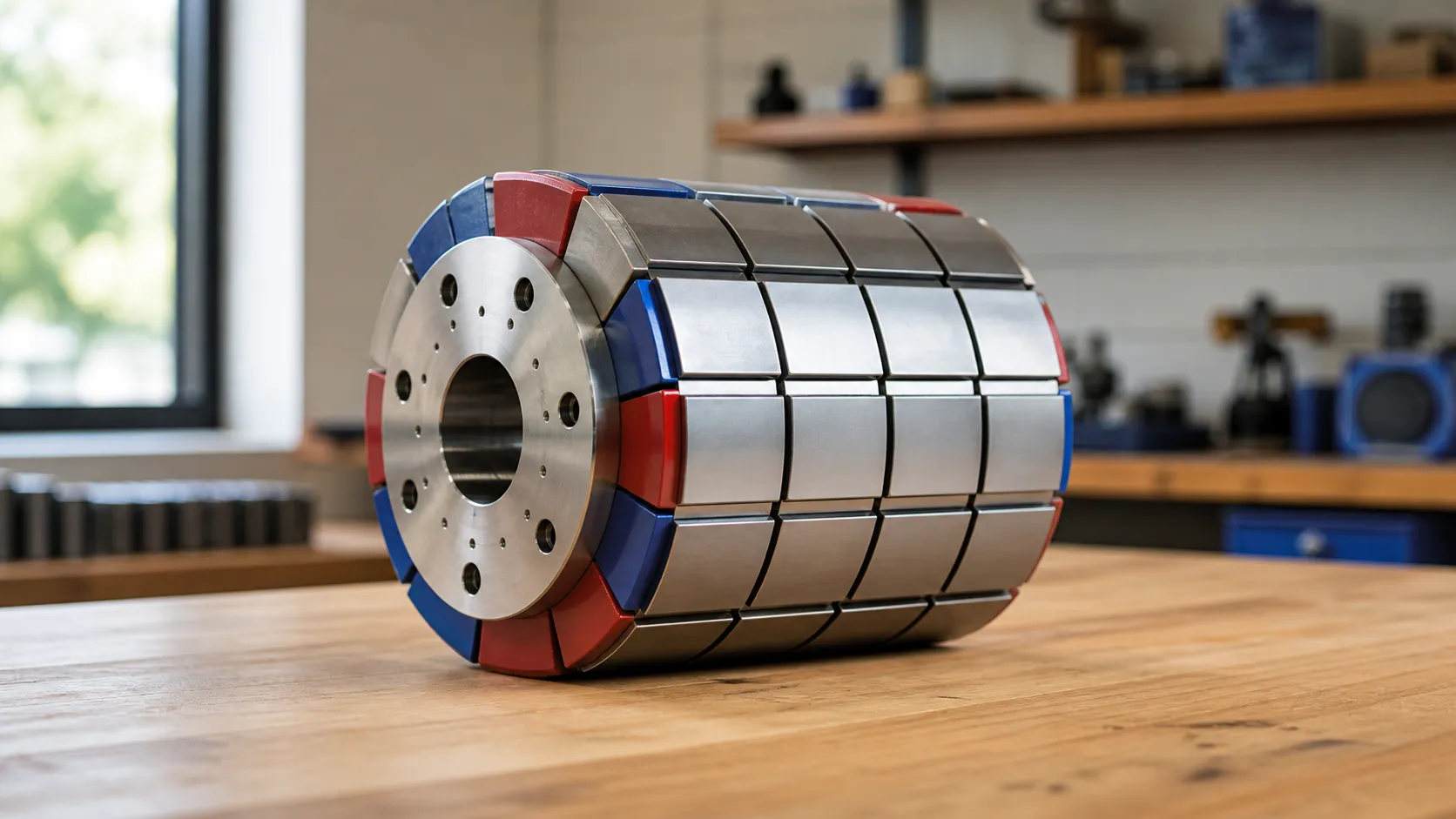
Zanechte komentář