
Are you pushing your compact actuator to its limits, only to watch your torque output suddenly drop off a cliff?
When integrating a frameless torque motor, frameless motor magnet demagnetization is one of the fastest—and most expensive—ways to permanently ruin a high-performance build. Because these motors rely entirely on your custom housing to pull heat away, a single peak current spike combined with trapped stator heat can silently push your rotor magnets past their point of no return.
In this guide, you’ll learn exactly what triggers irreversible torque loss, how to compare NdFeB and SmCo magnet grades for extreme environments, and the practical current and thermal limits you need to set to protect your hardware.
Let’s dive in!
Reversible vs. Irreversible Demagnetization in Frameless Motors
When a frameless torque motor loses torque output under heavy duty cycles, the root cause often comes down to frameless motor magnet demagnetization. To troubleshoot or prevent permanent flux loss on the bench, you first need to separate temporary thermal dips from permanent structural damage inside the rotor magnets.
Reading the Second-Quadrant B-H Curve (The “Knee” Point)
Every permanent magnet operates along the second quadrant of its B-H demagnetization curve, which tracks how magnetic flux density (Br, or remanence) holds up against opposing magnetic fields and heat.
-
- Reversible Flux Loss: As winding temperatures rise, a magnet naturally loses a small percentage of its flux density (Br). Once the motor cools back down, full magnetic strength returns with zero permanent harm.
- Irreversible Demagnetization Knee Point: Intrinsic coercivity (Hcj) measures a magnet’s resistance to being demagnetized. High heat pushes the Hcj curve downward, creating a sharp bend known as the “knee.” If the motor’s operating point drops below this knee under load, magnetic domains permanently misalign—and cooling the motor will never restore lost torque.
Why Frameless Architectures Face Unique Demagnetization Risks
Unlike traditional housed motors, a frameless stator-rotor kit ships without an enclosure, endbells, bearings, or built-in cooling fins. You integrate the active electromagnetic components directly into your own mechanical assembly.
In tightly packaged robotics joints, cobot actuators, and aerospace gimbals, space constraints often leave minimal room for heat sinks or airflow. Because the rotor sits directly inside the stator bore with no external cooling path, heat from peak torque bursts transfers straight across the air gap into the magnets, accelerating frameless motor magnet demagnetization much faster than in standard frame-mounted motors.
Primary Causes of Frameless Motor Magnet Demagnetization
When a compact joint actuator suddenly starts drawing higher phase current just to hold a routine payload, frameless motor magnet demagnetization is usually the root cause. Unlike housed motors with built-in cooling fins and rigid endbells, frameless kits rely completely on your surrounding mechanical structure to manage heat and magnetic stress. If one variable slips during integration, permanent flux loss follows quickly.
Thermal Overload and Air-Gap Heat Transfer
In tightly packaged joints, stator copper losses ($I^2R$) are the biggest threat to rotor health. Because a frameless rotor sits inside a narrow air gap without dedicated airflow, radiant heat from the stator windings transfers straight into the permanent magnets.
-
- Exceeding Tmax: Once heat pushes the magnets past their maximum continuous operating temperature ($T_{max}$), their intrinsic coercivity ($H_{cj}$) drops sharply.
- Approaching the Curie Point: If a stalled actuator cooks the windings near the Curie temperature ($T_c$), the magnetic domains randomize completely, wiping out torque output for good.
Excessive Armature Reaction and Peak Current Spikes
Even if your rotor stays below its thermal limit, aggressive servo drive tuning can still ruin the magnets. Whenever your system demands an instantaneous peak torque spike—such as during an emergency stop or sudden direction reversal—the stator generates a heavy opposing d-axis armature reaction demagnetizing current.
-
- The Heat-Current Double Hit: A magnet running at 120°C needs only a fraction of the reverse magnetic field to cross its irreversible demagnetization knee point compared to a magnet at room temperature.
- High-Density Actuator Stress: In compact robotics and high-precision neodymium magnet assemblies for microrobots, tight current loops leave almost zero margin when peak amps hit warm magnets.
Localized Edge-Effect Demagnetization
Demagnetization rarely happens evenly across an entire rotor pole. During severe load transients or a sudden three-phase short-circuit fault, reverse magnetic flux concentrates heavily at the sharp corners and trailing edges of individual magnet segments.
-
- Corner Flux Loss: Those outer edges cross the B-H curve knee point first, permanently trimming effective pole area.
- Ripple and Noise: Once the edges lose strength, you will immediately notice higher cogging, rougher torque ripple, and an uneven magnetic air gap.
Mechanical Shock, Vibration, and Adhesive Degradation
Sintered rare-earth magnets are strong magnetically, yet physically brittle like ceramic. When a robotic arm or mobile platform takes a hard, high-G mechanical impact, shock waves travel directly through the rotor hub into the bonded magnets.
-
- Micro-Cracking: Tiny fractures break up the continuous magnetic path and create localized eddy-current hot spots.
- Adhesive Failure: Repeated thermal cycling slowly degrades standard epoxies, letting magnets shift slightly in the air gap or detach under centrifugal load.
How to Diagnose a Demagnetized Frameless Rotor
When a joint starts running hot or pulling extra current out of nowhere, frameless motor magnet demagnetization is one of the first things I check on the bench. Because frameless motors are built directly into your housing without a sealed factory shell, subtle flux loss often hides behind servo tuning adjustments until performance drops off a cliff. Catching it early saves you from tearing down an entire robotic axis unnecessarily.
Field Symptoms in Motion Control Systems
Before you pull the rotor out of the assembly, your servo drive telemetry usually gives away the early warning signs of motor torque constant Kt degradation:
-
- Higher phase current draw for standard loads: If your axis suddenly needs 10% to 15% more current to hold the exact same payload or hit the same acceleration profile, your magnets have likely lost magnetic flux density.
- Unexplained operating temperature rises: Because copper losses scale with the square of the current, even a small drop in magnet strength forces the drive to pump more amps into the windings, creating a feedback loop of extra heat.
- Increased torque ripple or acoustic noise: Partial or uneven flux loss across the rotor poles throws off the magnetic balance, which shows up as cogging, low-speed vibration, or an unfamiliar whine under load.
Step-by-Step Bench Test for Measuring Back-EMF (Ke)
The fastest way to confirm back-EMF constant Ke drop is an open-circuit spin test on the bench. Since back-EMF is directly proportional to the rotor’s magnetic flux, any permanent drop in voltage proves the magnets are damaged.
-
- Disconnect the motor phases: Unplug all three power leads (U, V, and W) from the servo drive so the stator windings are completely open-circuit with zero load.
- Back-drive the rotor at a known constant RPM: Couple the shaft to a drill press, test fixture, or secondary drive motor and spin it at a steady, repeatable speed (for example, 1,000 RPM).
- Measure line-to-line voltage (VLL) on an oscilloscope: Probe across two phases (U-V, V-W, and W-U) to capture the peak-to-peak or RMS sinusoidal voltage waveform.
- Compare against baseline specs: Calculate your measured Ke (Volts per kRPM) and compare it to your original datasheet or a known-good reference unit; a drop greater than 3% to 5% confirms irreversible demagnetization.
Gaussmeter Surface Flux Mapping
If your back-EMF test looks borderline—or if you suspect a localized fault like a short-circuit spike damaged just one section of the rotor—you need to inspect the poles directly. This is especially important when validating custom assemblies or comparing radial designs against https://nbaem.com/high-performance-axial-flux-magnets-for-https://nbaem.com/high-performance-axial-flux-magnets-for-motors/”>high-performance axial flux magnets for motors, where pole-to-pole uniformity dictates smooth torque delivery.
-
- Zero the Hall-effect probe: Calibrate your Gaussmeter away from stray magnetic fields and keep the probe tip flat against a non-magnetic spacer so your standoff distance stays identical on every reading.
- Scan each pole center: Slowly index the rotor by hand and record the peak flux density (in Gauss or Tesla) at the geometric center of every North and South pole.
- Check pole corners and edges: Sweep along the leading and trailing edges of each magnet segment, as localized reverse fields almost always demagnetize the corners first before affecting the center.
- Look for asymmetry: A healthy rotor shows consistent peak readings within 2% to 3% across all poles, while a single weak pole or sharp drop at the magnet edges pinpoints exact localized damage.
Magnet Material and Grade Selection to Prevent Demagnetization
Picking the wrong magnet grade is one of the fastest ways to ruin a prototype on the dyno. When you push high current into a tightly packed actuator, choosing the right permanent magnet chemistry is your primary defense against frameless motor magnet demagnetization.
High-Coercivity Neodymium (NdFeB) Grades
Standard N-series NdFeB magnets (like N42 or N52) offer high magnetic strength at room temperature, but they lose their intrinsic coercivity (Hcj) fast once winding heat crosses the air gap. At around 80°C, their B-H curve knee point shifts upward, leaving the rotor vulnerable to permanent flux loss during heavy peak-torque spikes.
To survive real-world thermal loads, we move up to high temperature neodymium magnet grades (UH, EH, AH):
-
- SH Series (up to 150°C): Good baseline for moderate duty cycles with decent housing heat dissipation.
- UH Series (up to 180°C): Our standard go-to for compact robotics and cobot joints running high continuous currents.
- EH Series (up to 200°C): Built for tight actuator envelopes where stator copper losses bake the rotor.
- AH Series (up to 220°C–230°C): Maximum thermal resistance available in sintered NdFeB for severe transient overloads.
These grades rely on heavy rare-earth elements—specifically Dysprosium (Dy) and Terbium (Tb)—introduced via grain boundary diffusion. This process boosts Hcj right at the grain edges where demagnetization starts, without severely sacrificing your remanence (Br) or motor torque constant (Kt).
Samarium Cobalt (SmCo) for Extreme Thermal Stability
When a frameless torque motor runs in environments where NdFeB hits its thermal wall, we switch to Samarium Cobalt (Sm2Co17). Unlike neodymium, SmCo maintains a flat, linear second-quadrant demagnetization curve even under extreme heat and heavy reverse magnetic fields.
We specify Sm2Co17 rotors for applications where cooling is nearly impossible or ambient temperatures are brutal:
-
- Aerospace and defense actuators operating near turbine heat or without convective airflow.
- Downhole drilling tools exposed to 200°C+ geothermal conditions.
- High-vacuum semiconductor equipment where outgassing coatings and active liquid cooling are off-limits.
Because SmCo naturally resists oxidation, you also eliminate the risk of nickel or epoxy coating delamination peeling off inside tight radial air gaps. For engineers weighing similar high-temperature magnetic assemblies, our https://nbaem.com/magnetic-coupling-types-and-https://nbaem.com/magnetic-coupling-types-and-selection-guide/”>magnetic coupling types and selection guide breaks down how different rare-earth grades hold up under thermal and mechanical stress.
NdFeB (UH/EH) vs. SmCo Comparison for Frameless Rotors
Deciding between NdFeB vs SmCo magnets for motors comes down to balancing peak torque density against thermal safety margins and budget.
| Selection Factor | High-Temp NdFeB (UH / EH Grades) | Samarium Cobalt (Sm2Co17) |
|---|---|---|
| Max Operating Temp | 180°C to 200°C | 300°C to 350°C |
| Intrinsic Coercivity (Hcj) | High (25–30+ kOe at 20°C, drops rapidly with heat) | High (18–25+ kOe, stays stable at high heat) |
| Temp Coefficient of Br | -0.09% to -0.11% per °C | -0.03% to -0.04% per °C |
| Corrosion Resistance | Low (requires Ni-Cu-Ni, epoxy, or parylene coating) | Excellent (no surface coating required) |
| Mechanical Brittleness | Moderately brittle | Very brittle (requires careful rotor assembly) |
| Relative Material Cost | Moderate to High (driven by Dy/Tb content) | Very High (driven by Cobalt and Samarium pricing) |
If your stator windings stay under 160°C and you need maximum torque per cubic millimeter, UH or EH grade NdFeB gives you the highest air-gap flux density. If your thermal model shows rotor temperatures pushing past 180°C—or if you cannot afford torque constant drift across wide temperature swings—Sm2Co17 is the safer engineering choice.
System-Level Engineering Safeguards During Integration
Even the best magnet grade will fail if you drop it into a poorly cooled housing or run an aggressive servo loop without guardrails. When we help engineers integrate frameless kits into tight robotics joints, we always lock down four system-level safeguards to prevent frameless motor magnet demagnetization before it starts.
Optimizing Housing Thermal Interfaces
A frameless stator relies entirely on your surrounding mechanical housing to pull heat away from the copper windings. If heat gets trapped in the stator, it radiates straight across the air gap into the rotor magnets.
-
- Maximize contact area: Machine tight, uniform bores so the outer stator lamination stack sits flush against the housing wall with minimal radial air gaps.
- Use thermal gap fillers: Apply high-conductivity thermal potting compounds or thin interface pads between the stator OD and the housing to eliminate insulating air pockets.
- Create direct heat paths: Route heat toward external structural metal or liquid-cooled plates rather than trapping the motor inside sealed composite or plastic enclosures.
Servo Drive Current Limiting and I2t Protection
High-torque transients generate massive opposing magnetic fields that can push hot magnets past their demagnetization knee point in milliseconds. You need your servo drive to actively protect the rotor when temperatures climb.
-
- Program temperature-derated limits: Set up dynamic current foldback curves in your drive controller that automatically reduce the peak current limit as stator winding temperature rises.
- Tune I2t protection: Configure strict I2t thermal integration limits so the drive trips or throttles output before sustained stall currents overheat the rotor assembly.
Redundant Stator Temperature Sensing
Relying on a single thermistor glued to the outside of a motor housing gives you a delayed, inaccurate picture of rotor risk. By the time the outer housing feels hot, the internal magnets may already be taking permanent flux damage.
-
- Embed sensors in end-windings: Place dual PT1000 RTDs or fast-response PTC thermistors directly inside the stator end-windings where copper losses peak first.
- Build in redundancy: Wire two independent sensors so a single broken lead wire never leaves your control loop flying blind during heavy-duty cycles.
Magnet Segmentation and Halbach Array Considerations
In high-speed frameless torque motors, rapidly changing slot harmonics induce swirling eddy currents inside the permanent magnets themselves. This internal heating happens right inside the rotor, bypassing your housing cooling altogether.
-
- Segment the magnets: Split larger arc magnets into smaller, electrically insulated axial or circumferential pieces to break up eddy-current loops and slash rotor magnet eddy current heating.
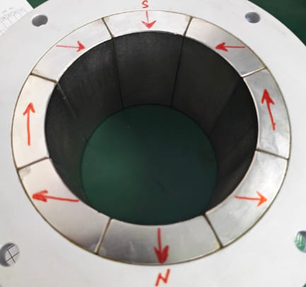
- Evaluate Halbach arrays: For compact, high-flux designs, a Halbach array concentrates magnetic flux toward the air gap while reducing back-iron thickness—though you must verify that every angled segment has high enough intrinsic coercivity to withstand opposing fields from neighboring poles.
Custom Frameless Motor Magnet Engineering and Quality Verification
Off-the-shelf magnets are the fastest way to run into frameless motor magnet demagnetization during high-load testing. Standard catalog parts rarely match the exact thermal limits or peak-current spikes of a custom robotic or gimbal envelope.
Custom Magnet Engineering and Grade Matching
We engineer rotor magnets around your real-world duty cycle rather than relying on generic room-temperature ratings. Depending on your operating heat and torque demands, we tailor the geometry and alloy grade to hold magnetic flux steady under load:
-
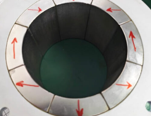
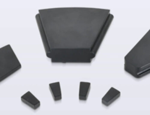
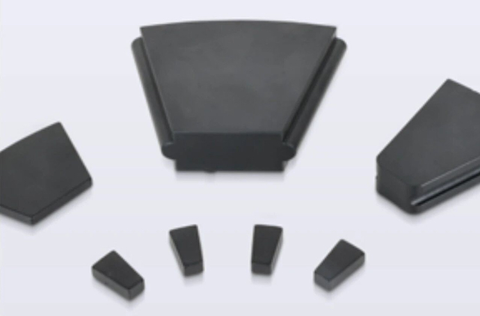
- Arc Segments and Multi-Pole Rings: Custom-sized sintered NdFeB and SmCo geometries built to fit tight radial air gaps and maximize torque density.
- Halbach Arrays: Custom-oriented pole assemblies that concentrate flux on the stator side while cutting back-iron weight and stray magnetic fields.
- Duty-Cycle Grade Matching: Selecting high-coercivity NdFeB grades (SH, UH, EH, AH) or Samarium Cobalt based on your exact peak armature current and worst-case winding temperatures.
Quality Assurance and B-H Curve Verification
A grade stamp on a datasheet does not guarantee performance once the rotor heats up on the bench. Every production batch goes through strict verification before shipping so you do not get surprised by early motor torque constant Kt degradation:
-
- Hysteresisgraph Testing: Batch-level verification of remanence (Br), normal coercivity (Hcb), and intrinsic coercivity (Hcj) across your target operating temperatures to confirm the B-H demagnetization curve knee point stays safely out of reach.
- Precision Mechanical Tolerances: Tight dimensional control following strict magnet geometric dimensioning and tolerancing standards to ensure uniform air gaps, balanced rotation, and reliable rotor bonding.
Frequently Asked Questions About Frameless Motor Magnet Demagnetization
When we troubleshoot torque loss on the test bench, the same practical questions always come up. Here is a quick diagnostic breakdown of what we see in the field, followed by specific answers for your motor builds.
| Symptom or Condition | Threshold / Trigger | Permanent Damage Risk | Field Fixability |
|---|---|---|---|
| Back-EMF ($K_e$) Drop | Greater than 3%–5% at room temp | High (Irreversible loss) | Requires rotor replacement |
| Standard N-Grade NdFeB Temp | Above 80°C | High (Rapid knee-point shift) | Cannot re-magnetize in-housing |
| Peak Current Spike ($I_q$ / $I_d$) | Exceeds $H_{cj}$ limit at operating temp | High (Localized corner loss) | Requires rotor replacement |
How much back-EMF (Ke) drop confirms irreversible magnet demagnetization?
A room-temperature drop of more than 3% to 5% in line-to-line back-EMF voltage ($V_{LL}$) confirms permanent flux loss. Always let the motor cool completely to ambient temperature (around 20°C–25°C) before testing. Magnets naturally lose some flux temporarily when hot, so testing a warm rotor will give you a false alarm.
Can a demagnetized frameless motor rotor be re-magnetized in the field?
No, you cannot re-magnetize a frameless rotor once it is bonded and assembled. Re-magnetizing rare-earth magnets requires massive, specialized pulse magnetizing fixtures capable of delivering several Tesla of magnetic field strength. In practice, a permanently demagnetized rotor has to be pulled and replaced.
What stator temperature puts standard Neodymium (NdFeB) magnets at risk of demagnetization?
Standard N-grade Neodymium magnets start losing flux permanently right around 80°C. Because frameless motors lack built-in housings and rely on your mechanical structure to pull heat away, stator copper losses easily push rotor temperatures past that mark. For tight robotic joints or actuators, we always recommend stepping up to UH, EH, or AH grades rated for 180°C to 220°C.
When should engineers choose Samarium Cobalt (SmCo) over high-temperature NdFeB for a frameless rotor?
Choose SmCo ($Sm_2Co_{17}$) whenever your continuous operating environment exceeds 200°C or sits in a harsh, corrosive atmosphere. While high-grade NdFeB offers higher peak torque density at moderate temperatures, SmCo resists thermal demagnetization up to 300°C–350°C and requires zero corrosion coating. It is our go-to choice for aerospace actuators, downhole tools, and high-vacuum systems.
How do servo drive peak current spikes cause demagnetization even below maximum temperature ratings?
High peak current demands generate a strong opposing magnetic field (armature reaction) that directly fights the rotor magnets. As a magnet heats up—even if it stays safely below its maximum temperature rating—its intrinsic coercivity ($H_{cj}$) drops significantly. If your servo drive pushes a massive current spike while the rotor is warm, that reverse field pushes the magnet’s trailing edges past the B-H demagnetization curve knee point. To understand how thermal stress and reverse fields interact across different motor topologies, review our technical breakdown on the [primary causes of demagnetization in permanent magnet motors](https://nbaem.com/cause-demagnetization
Related Links:

 English
 German
 Vietnamese
 Spanish (Mexico)
 Russian
 Turkish
 Polish
 Hindi
 Thai
 Malay
 Korean
 Japanese
 French
 Czech
 Danish
 Dutch
 Finnish
 Italian
 Portuguese (Brazil)
 Portuguese (Portugal)
 Slovenian
 Ukrainian
 Hebrew
 Scottish Gaelic
 Hungarian
 Tagalog
 Spanish (Spain)
 Serbian
 Indonesian
 Slovak
 Dutch (Belgium)
 Persian
 Arabic
 Romanian
 Estonian
 Greek
 Bulgarian
Leave A Comment