
Vuoi massimizzare la densità di coppia, ridurre il peso del componente o eliminare campi parassiti indesiderati nelle tue realizzazioni elettromagnetiche? I raggruppamenti magnetici standard spesso non soddisfano le richieste quando la tua applicazione richiede un’efficienza di campo al massimo.
Padroneggiare una configurazione di magneti a matrice Halbach cambia le regole del gioco. Ruotando spazialmente i vettori di magnetizzazione, questa progettazione raddoppia la densità del flusso magnetico su un lato attivo mentre lo annulla virtualmente sul lato opposto—consegnando una concentrazione massima del campo senza aggiungere peso né richiedere potenza attiva.
In questa guida, imparerai come selezionare e ottimizzare le giuste disposizioni—dalle reti piane to cilindri Halbach cilindrici, confrontando schema 4-pattern (90°) e 8-pattern (45°) passi di rotazione per aumentare l’efficienza in motori ad alte prestazioni, sistemi a levitazione magnetica e dispositivi industriali specializzati.
Andiamo subito.
Cos’è una configurazione di magnete a matrice Halbach?
Definiamo una configurazione di magneti a matrice Halbach come una disposizione specializzata di magneti permanenti che concentra il flusso magnetico su un lato mentre lo riduce quasi a zero sull'altro. Ruotando la direzione di magnetizzazione dei magneti adiacenti, creiamo un pattern di flusso magnetico autocoperto e unidirezionale senza la necessità di pesanti piaste di supporto in ferro.
Comprendere la Rotazione del Campo Magnetico di 90 Gradi
Nella disposizione magnetica standard, i campi magnetici irradiamo in modo simmetrico da poli Nord a Poli Sud. Nelle nostre disposizioni Halbach, spostiamo la orientamento del campo magnetico di 90 gradi in modo sequenziale attraverso blocchi adiacenti (0°, 90°, 180°, 270°).
-
- Rotazione Vettoriale: Il vettore magnetico ruota continuamente attraverso la sequenza lungo la matrice di magneti permanenti.
- Combinazione Costruttiva: I campi magnetici si sommano sulla faccia attiva di lavoro.
- Cancellazione Distruttiva: I campi magnetici opposti si annullano reciprocamente sul lato opposto non attivo.
Disposizioni Magnetiche Standard vs. Impostazioni Halbach
| Caratteristica | Array Magnetico Standard | Configurazione magnetica dell'array di Halbach |
|---|---|---|
| Distribuzione del flusso | Simmetrico (campo uguale su entrambi i lati) | Asimmetrico (Magneta a flusso unilaterale effetto) |
| Forza del campo | Densità di flusso standard | Fino a doppia densità di flusso sul lato forte |
| Schermatura in ferro posteriore | Richiede gioghi in acciaio/ferro pesanti | Richiesti gioghi pesanti minimi o nessuno |
| Efficienza del peso | Rapporto forza-peso inferiore | Rapporto forza-peso massimo |
Vantaggi pratici dell'ingegneria del flusso unilaterale
-
- Riduzione drastica del peso: Eliminare i giunti di supporto in acciaio ingombranti riduce il peso complessivo del sistema.
- Prevenzione del campo estraneo: Protezione magnetica integrata l'efficienza dello schermaggio magnetico protegge i componenti elettronici adiacenti dall'interferenza magnetica.
- Massima performance magnetica: Dirigendo tutte le fluenze magnetiche disponibili verso il lato di lavoro si ottiene la massima densità di forza per unità di volume.
Come funziona l'array di Halbach?
Quando guardiamo a una configurazione magnetica dell'array di Halbach, il segreto delle sue prestazioni risiede nella manipolazione dei vettori spaziali. Invece di allineare i magneti con tutti i poli nord che guardano nella stessa direzione, ruotiamo il rotazione del dipolo magnetico di 90 gradi sequenzialmente lungo ogni blocco adiacente nel matrice di magneti permanenti.
Principio Matematico della Somma di Vettori Magnetici
La meccanica sottostante si basa sull'aggiunta vettoriale magnetica. Man mano che il flusso magnetico viaggia tra magneti adiacenti, spostandosi sistematicamente orientamento del campo magnetico modifica come i campi fisici si sovrappongono:
-
- Sovrapposizione Costruttiva: Le coppie di vettori di flusso si combinano nella stessa direzione sul lato attivo per aumentare la potenza.
- Interferenza Distruttiva: Vettori opposti cancellano le linee di campo sul lato non attivo.
Comprendere i percorsi vettoriali è essenziale per build ad alte prestazioni. Puoi vedere dinamiche magnetiche strutturali simili in azione esaminando come funzionano i gruppi di aste magnetiche in applicazioni pratiche di canalizzazione del flusso.
Campi che si annullano sul lato debole
Imponendo uno spostamento vettoriale continuo di 90 gradi, le linee di flusso sulla superficie posteriore ricircuiscono nei magneti adiacenti prima di espandersi all'esterno.
-
- Leaking quasi zero del campo: L'interferenza distruttiva riduce i campi magnetici estranei sulla faccia posteriore a quasi zero.
- Vantaggi di auto-schermatura: Massimizza l'efficienza dello schermaggio magnetico senza richiedere robuste piastrine posteriori in acciaio o gioghi in ferro, riducendo drasticamente la massa complessiva del sistema.
Aumentare l'intensità del campo sul lato forte
Sulla faccia attiva, i vettori orizzontali e verticali si combinano in modo costruttivo. Questo crea una vera magnete a flusso unidirezionale con eccezanti guadagni di densità di flusso:
| Caratteristica magnetica | Layout magnetico standard | Configurazione del magnete a matrice Halbach |
|---|---|---|
| Distribuzione del campo | Simmetrico (top 50% / bottom 50%) | Asimmetrico (~90%+ sul lato attivo) |
| Forza di flusso relativa | Linea di base (1.0x) | Fino a 1.4x più forte sul lato forte |
| Schermatura in ferro posteriore | Richiede (aumenta il peso) | Non necessario (annullamento incorporato) |
Otteniamo al massimo concentrazione del flusso magnetico precisamente dove serve, offrendo una densità di flusso più alta senza aggiungere un'oncia di peso in più.
Tipi chiave di configurazione della magnete array Halbach
Raggruppiamo ogni configurazione magnetica dell'array di Halbach in tre configurazioni strutturali principali a seconda che il flusso debba viaggiare su una superficie piana, all'interno di un cilindro o intorno a un albero in rotazione.
Array di Halbach lineare
A array di Halbach lineare posiziona magneti permanenti fianco a fianco su un piano piatto.
-
- Orientazione magnetica: Ruota il vettore di campo di 90 gradi ad ogni blocco magnetico adiacente.
- Comportamento del flusso: Crea una superficie magnetica potente su un lato mantenendo l'opposto lato praticamente inattivo.
- Usi principali: Levitazione del treno Maglev, guide a motore lineare ad alta velocità e tavole di posizionamento di precisione.
- Vantaggio principale: Fornisce la massima forza di trattenimento e spinta senza necessità di un pesante scudo in back-iron.
Per capire come questi vettori ruotati si sommano matematicamente, esplora come funzionano i magneti a matrice Halbach nei sistemi reali di movimento lineare.
Matrice Halbach circolare e cilindri Halbach
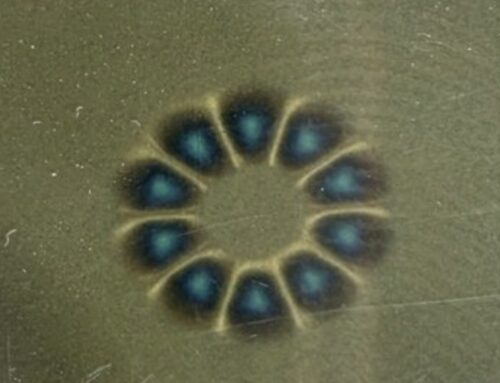
Pieghando la sequenza piatta in un anello continuo si ottiene una cilindro di Halbach.
-
- Concentrazione del flusso interno: Concentra un campo magnetico estremamente uniforme all'interno esatto del foro del cilindro, annullando completamente il campo esterno.
- Concentrazione del flusso esterno: Dirige il campo verso l'esterno mentre schermza la cavità interna.
- Usi principali: Apparecchiature di risonanza magnetica, acceleratori di particelle e accoppiamenti magnetici senza contatto.
Rotori Halbach in Motori e Generatori
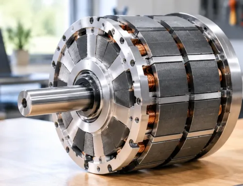
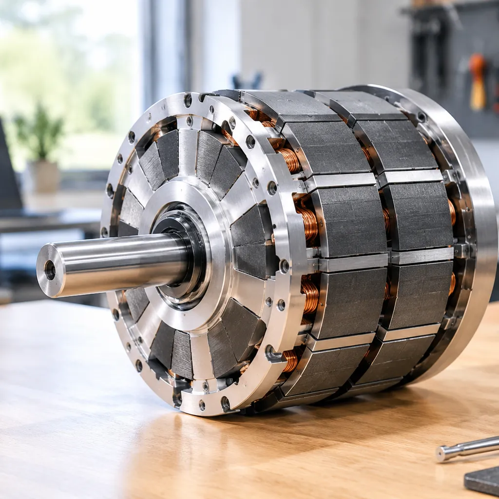
Aplicando questa disposizione a una rotore Halbach a spazzole motore brushless ridefinisce la progettazione di azionamenti ad alte prestazioni.
-
- Forma d'onda sinusoidale: Pubblica una distribuzione del campo magnetico pulita che riduce drasticamente il cogging torque e le vibrazioni del motore.
- Densità di coppia aumentata: Produce una densità di flusso nel vuoto d'aria significativamente superiore rispetto agli ordinamenti standard magnetici radiali.
- Usi principali: Torsi di alimentazione per veicoli elettrici, propulsione di droni e attuatori aerospaziali.
Quando si scelgono blocchi di terre rare per assemblaggi di motori ad alta rpm, selezionare quali materiali magnetici sono migliori per gli array di Halbach assicura stabilità contro temperature operative elevate e rischi di smagnetizzazione.
Confronto rapido delle configurazioni Halbach
| Tipo di configurazione | Area di focus del campo | Vantaggio chiave | Applicazioni Tipiche |
|---|---|---|---|
| Array lineare | Una superficie piana | Elimina il peso di ferro posteriore | Binari a levitazione magnetica, actuatori lineari |
| Cilindro Halbach | Interno o esterno forato concentrato | Zero dispersione di flusso esterno | Dispositivi MRI, messa a fuoco del raggio |
| Rotore Halbach | Circonferenza dell'intercapo d'aria | Bassa cogging, coppia massima | Motori BLDC, propulsione per veicoli elettrici |
Come progettare e assemblare un array magnetico Halbach
Costruire un efficiente configurazione magnetica dell'array di Halbach richiede una selezione precisa dei materiali, un allineamento angolare rigoroso e fissaggio specializzato. Analizziamo i passaggi di ingegneria chiave per costruire un array affidabile ad alto output.
Selezione delle classi di magneti al neodimio
Scegliere la giusta classe equilibra intensità del campo, limiti di temperatura e durata meccanica lungo la assemblaggio di magneti al neodimio:
-
- Classi N35 a N42: eccellente scelta per progetti sensibili al costo o applicazioni che operano vicino a temperature più alte.
- Classi N45 a N52: fornisce picco concentrazione del flusso magnetico per spazi compatti. Tieni presente che classi più alte come N52 sono più fragili e sensibili agli urti durante l’installazione.
Calcolo degli angoli di orientamento del magnete
Per costruire una disposizione funzionale array di Halbach lineare o cilindrica, i magneti adiacenti devono seguire una rigorosa sequenza di rotazione del campo magnetico di 90 gradi:
-
- Blocco 0°: vettore magnetizzato rivolto direttamente verso la faccia operativa attiva.
- Blocco 90°: vettore ruotato in orizzontale verso destra.
- 180° Blocco: Vettore rivolto direttamente verso il basso allontanandosi dalla faccia attiva.
- Blocco a 270°: Vettore ruotato orizzontalmente verso sinistra.
Questa ripetizione rotazione del dipolo magnetico fissa il campo magnetico sul lato di lavoro cancellando il flusso sulla faccia posteriore non funzionante.
Gestione delle forze Repulsive e serraggio strutturale
Spingere magneti opposti insieme genera giorni di taglio estremi e forze repulsive durante l'installazione.
-
- Dispositivi di assemblaggio: Usiamo mascherine di allineamento non magnetiche—tipicamente realizzate in alluminio 6061 lavorato a precisione o ottone—per premere ogni blocco in posizione in sequenza.
- Serraggio meccanico: La forza magnetica degraderà giunti incollati nel tempo sotto cicli termici. Rafforziamo gli array con bande in acciaio inossidabile, manicotti in fibra di carbonio o involucri strutturali, simili ai variatori di coppia a contatto non usati nei sistemi di accoppiamento magnetico minerario.
Opzioni consigliate di housing e di adesivi
| Componente | Materiale Raccomandato | Funzione |
|---|---|---|
| Collante | Acetato strutturale a due componenti o epossi ad alta cross-imping | Tratta blocchi contro lo stress di taglio laterale permanente |
| Alloggiamento | Alluminio, acciaio inossidabile 316, PEEK | Materiali non magnetici prevengono cortocircuiti magnetici |
| Incapsulamento | Resina epoxy in potting a vuoto o avvolgimento in fibra di carbonio | sigillano blocchi di neodimio contro l'ossidazione e gli shock meccanici |
Applicazioni reali di array di magneti Halbach
Progettiamo assemblaggi di magneti permanenti per fornire la massima densità di flusso dove lo spazio e il peso sono strettamente limitati. La singolare rotazione del campo di configurazione magnetica dell'array di Halbach lo rende la scelta primaria nelle industrie high-tech in tutto il mondo.
Veicoli elettrici e azionamenti dei motori
Nell'odierna mobilità elettrica, la densità di potenza è critica. Integramo questi alloggiamenti specializzati in motori di trazione EV ad alte prestazioni per ottimizzare la performance.
Maggiore efficienza: Concentra il flusso direttamente verso lo statore, riducendo la perdita di energia.
Riduzione del peso: Elimina i pesanti giunti di rientro in ferro, estendendo l'autonomia complessiva.
accelerazione fluida: L'integrazione di rotore Halbach a spazzole motore brushless riduce la coppia cogging per una fornitura di potenza senza interruzioni.
Treni Maglev e sistemi di trasporto pubblico
I sistemi ad alta velocità dipendono da soluzioni specializzate configurazioni magnetiche a levitazione magnetica per un levitazione e una guida affidabili.
Levitação passiva: Le piste che impiegano disposizioni lineari generano forze di sollevamento enormi man mano che aumenta la velocità del veicolo.
Precisione di guida: Mantiene l’allineamento del treno lungo la guida senza contatto meccanico.
Acceleratori di particelle
L'hardware scientifico avanzato richiede campi magnetici intensi e altamente uniformi.
Steering del fascio: Gli acceleratori di particelle utilizzano arrangiamenti circolari per focalizzare i fasci di particelle cariche con un’estrema precisione.
Macchine MRI compatte: Genera campi forti ed omogenei richiesti per i dispositivi medici portatili di prossima generazione.
elettronica di consumo e chiusure industriali
Quando l’efficienza dello spazio è importante, utilizzare un magnete a flusso unidirezionale Il layout fornisce la massima forza di trattenuta in profili sottili di prodotto.
Attacchi/Accessori per dispositivi Protegge in modo sicuro accessori per tablet con attacco a snap-on e hardware modulare in modo ordinato.
Ingranaggio di precisione: Powers ultra-strong chiusure magnetiche per porte e assolentatori specializzati che mantengono i campi magnetici contenuti senza disturbare l’elettronica sensibile nelle vicinanze.
Pro e contro della configurazione di magneti ad array di Halbach
Valutiamo regolarmente i/le configurazione magnetica dell'array di Halbach bilanciare la massima intensità del campo magnetico contro la complessità di produzione per applicazioni hardware compatte.
Vantaggi Chiave
-
- Densità di flusso magnetico massima: Concentrating field lines onto a single working face nearly doubles the concentrazione del flusso magnetico senza aggiungere volume fisico.
- Riduzione del peso e autodotato di schermatura: La quasi completa cancellazione del campo sul lato debole fornisce alta l'efficienza dello schermaggio magnetico, permettendoci di eliminare i ruotismi posteriori in ferro pesanti.
- Alta efficienza spaziale: L’emissione di campo di picco in spazi ristretti consente azionamenti e attuatori più leggeri e potenti.
Svantaggi chiave
-
- Pericoli di assemblaggio e complessità: Forzare vettori magnetici repellenti nelle rotazioni dell’obiettivo richiede accessori di allineamento specializzati e legatura ad alta resistenza.
- Sensibilità alla temperatura: Come la maggior parte delle magneti ad alte prestazioni assemblaggi di magneti al neodimio, temperature operative elevate possono rischiare la demagnetizzazione se i limiti termici sono superati.
- Costi di produzione più elevati: L’allineamento magnetico multi-angolo di precisione aumenta i passaggi di lavorazione rispetto a un normale matrice di magneti permanenti.
Confronto di compromesso
| Metrica di Prestazione | Configurazione del magnete a matrice Halbach | Layout magnetico standard |
|---|---|---|
| Densità di flusso lato operativo | Concentrato (fino a 2x) | Anisometrico (uguale su entrambi i lati) |
| Protezione esterna necessaria | Minimo (self-protection) | Alta (richiede supporto in ferro) |
| Complessità di assemblaggio | Alta (Richiede atrezzi personalizzati) | Da basso a moderato |
| Peso complessivo del sistema | Leggero | Pesante |
| Costo di produzione | Superiore | Standard |
Domande frequenti sulle matrici Halbach
Quanto è più forte una matrice Halbach rispetto a una disposizione magnetica regolare?
Una corretta messa a punto configurazione magnetica dell'array di Halbach aumenta la densità di flusso magnetico di 1,4x a 2x (un boost 40% a 100%) sul lato attivo rispetto a un array magnetico permanente a nord-sud alternato di identico peso. Ruotando il vettore di campo, concentriamo quasi tutta l'energia magnetica utilizzabile su una superficie di lavoro. Per rivedere la matematica vettoriale fisica dietro questo reindirizzamento del flusso, consulta come funzionano i magneti a matrice Halbach in sistemi reali.
Riesci a costruire una matrice Halbach usando magneti rettangolari standard?
Sì. Non è necessario magneti curvi stampati su misura per costruire matrici funzionali. Blocchi rettangolari standard da un normale assemblaggio di magneti al neodimio funzionano in modo affidabile.
-
- Rotazione di 90 gradi: Posiziona i blocchi rettangolari adiacenti in modo che i loro vettori di magnetizzazione ruotino a passi di 90 gradi (0°, 90°, 180°, 270°).
- Ridirezione del flusso: Questo semplice layout crea un effetto magnete a flusso unidirezionale senza attrezzature personalizzate costose.
- Requisito di serraggio: Poiché i magneti adiacenti si spingono lateralmente l'uno contro l'altro durante l'installazione, sono necessari dispositivi di serraggio meccanici pesanti.
Le matrici Halbach richiedono schermatura esterna con yoke in ferro?
In genere no. Il vantaggio principale della scelta di una array Halbach lineare or rotore Halbach è dotato di schermatura integrata.
-
- Cancellazione del campo: Il campo magnetico sul lato non operativo si annulla naturalmente verso livelli prossimi a zero.
- Risparmio di peso: Eliminare i retroilluminatori di ferro pesanti riduce drasticamente il peso totale del sistema, rendendo questi array ideali per applicazioni mobili e aerospaziali. Scopri di più su dove si utilizzano magneti a array Halbach in diversi settori sensibili al peso.
- Casi speciali: Il ferro posteriore sottile viene aggiunto solo quando l'alloggiamento è posto vicino a elettroniche di controllo sensibili sul lato debole.
Qual è la differenza tra un array Halbach 1D e 2D?
| Caratteristica | Array Halbach 1D | Array Halbach 2D |
|---|---|---|
| Asse di rotazione magnetica | Ruota lungo un unico percorso lineare o circolare | Ruota lungo entrambi gli assi della griglia X e Y simultaneamente |
| Distribuzione del flusso | Dirige il flusso su una singola piastra 2D | Forma una griglia di campo 3D altamente concentrata e localizzata |
| Usi comuni | Tracciati magnetici a levitazione guidano, azionamenti lineari, motori senza spazzole | Stazioni planari multi-assiali, tavole di levitazione, ottica di precisione |
| Complessità di assemblaggio | Moderato (richiede serraggio su un solo asse) | Alto (richiede contenimento di forze multi-direzionali) |
 Italian
  English
  German
  Vietnamese
  Spanish (Mexico)
  Russian
  Turkish
  Polish
  Hindi
Hindi  Thai
Thai  Malay
Malay  Korean
  Japanese
  French
  Czech
Czech  Danish
  Dutch
Dutch  Finnish
  Portuguese (Brazil)
  Portuguese (Portugal)
  Slovenian
  Ukrainian
  Hebrew
  Scottish Gaelic
  Hungarian
  Tagalog
  Spanish (Spain)
  Serbian
  Indonesian
  Slovak
  Dutch (Belgium)
  Persian
  Arabic
  Romanian
  Estonian
  Greek
Greek  Bulgarian

Lascia un commento