
Ever wondered how a transformer transfers megawatts of power from one circuit to another without a single physical wire connection? The answer lies in magnetic coupling in transformer designs—a fundamental electromagnetic process that enables efficient power transfer alongside complete galvanic isolation.
Here is the exact step-by-step physics behind how we harness magnetic coupling to transfer electrical energy reliably.
How Magnetic Coupling Works: Step-by-Step Physics
Step 1: AC Current Input & Dynamic Magnetic Field Generation
Every magnetic coupling process starts at the primary winding. When an alternating current (AC) flows through this input coil, it creates an oscillating magnetic field. Because AC continually changes direction and magnitude, the resulting magnetic field is dynamic—expanding and collapsing in tandem with the input waveform.
-
- Key Mechanism: The rate of current change directly dictates the strength and frequency of the magnetic field.
- Core Requirement: Energy transfer relies on this continuous field variation; a static DC current cannot sustain dynamic coupling.
Step 2: Flux Concentration via High Permeability Core
In open air, magnetic fields disperse in all directions, causing severe energy loss. To maximize magnetic coupling, we route this energy through a high magnetic permeability core (such as laminated silicon steel or advanced soft magnetic alloys).
-
- Flux Channeling: The core provides a low-reluctance path, trapping and concentrating the magnetic flux linkage.
- Leakage Control: Confining the magnetic lines of force prevents flux leakage, ensuring the vast majority of generated energy travels straight to the output winding.
Step 3: Voltage Induction in Secondary Winding
As the dynamic magnetic flux travels through the core, it links directly with the secondary winding. This changing magnetic environment triggers Faraday’s Law of Electromagnetic Induction.
-
- EMF Generation: The time-varying magnetic flux cuts across the secondary coil turns, inducing an electromotive force (EMF) and generating a precise output voltage.
- Galvanic Isolation: Power moves strictly through magnetic flux, keeping the primary and secondary circuits completely isolated electrically.
Key Parameters Governing Magnetic Coupling
When we design high-efficiency transformers, key electrical parameters define how effectively magnetic energy moves between coils. Controlling these variables allows us to maximize energy transfer while minimizing unwanted loss.
Self-Inductance & Mutual Inductance
-
- Self-Inductance (L1, L2): The ability of an individual primary or secondary winding to induce voltage within itself when driven by varying AC current.
- Mutual Inductance (M): The measure of how effectively current changes in the primary winding induce a voltage across the secondary winding. High mutual inductance forms the backbone of effective magnetic coupling design.
Coupling Coefficient (k)
The coupling coefficient (k) quantifies the fraction of primary magnetic flux linkage that reaches the secondary winding. Its value stays strictly between 0 (complete isolation) and 1 (perfect flux transfer).
The mathematical relationship is calculated as: M = k * sqrt(L1 * L2)
Ideal vs. Real-World Coupling (k Value Breakdown)
| Coupling Class | k Factor Range | Physical Behavior | Primary Applications |
|---|---|---|---|
| Ideal Coupling | k = 1.0 | 100% flux linkage; zero leakage flux. | Theoretical models only. |
| Tight Coupling | 0.95 <= k < 1.0 | High-permeability core; minimal leakage flux. | Grid power transformers, step-up/down units. |
| Loose Coupling | k < 0.5 | Large air gaps; low magnetic linkage. | Wireless charging, resonant converters. |
Transformer Polarity: The Dot Convention
Winding orientation dictates voltage phase relationships between input and output terminals. We rely on the dot convention to maintain precise circuit polarity:
-
- In-Phase Condition: When current flows into the dotted primary terminal, the dotted secondary terminal instantly becomes positive.
- Phase Inversion: When current enters the undotted primary terminal, the dotted secondary terminal generates negative relative voltage.
Accurately matching polarity prevents signal cancellation and stops destructive circulating currents in parallel transformer configurations.
Efficiency Losses and Design Factors Affecting Coupling
Even with high magnetic permeability materials, no real-world system achieves perfect magnetic coupling in transformer applications. When we build and optimize high-efficiency transformers, several physical design factors prevent complete flux transfer from the primary to the secondary winding. Understanding these loss mechanisms allows us to maximize energy transfer and maintain a high coupling coefficient (k).
Leakage Flux and Leakage Inductance
Not all magnetic flux generated by the primary winding travels through the core to link with the secondary winding. Some flux escapes into the surrounding air—this is leakage flux.
-
- System Impact: Leakage flux creates leakage inductance, which behaves as an unwanted inductive impedance in series with the transformer windings.
- Efficiency Loss: Increased leakage flux lowers the total magnetic flux linkage (Φ), directly reducing the coupling coefficient below ideal levels.
- Design Control: We minimize leakage inductance through tight winding geometries, concentric coil arrangements, and high-permeability core designs.
Core Losses in Coupling Systems
Core losses occur within the magnetic core material itself during magnetic cycling. These losses dissipate energy as heat, lowering overall system efficiency.
| Loss Mechanism | Ursache | Engineering Solution |
|---|---|---|
| Eddy Current Loss | Induced circulating currents inside the conductive core material due to changing magnetic fields. | Use a laminated silicon steel core or high-resistivity ferrite materials to interrupt electrical paths. |
| Hystereseverlust | Energy required to reorient magnetic domains during every alternating current (AC) cycle. | Select specialized weiche magnetische Materialien with narrow hysteresis loops and low coercivity. |
Controlling core losses is critical in high-frequency transformer cores, where elevated operating frequencies accelerate temperature rise and energy dissipation.
Magnetic Core Saturation
Every magnetic core material has a maximum magnetic flux density limit. When the magnetic field strength increases beyond this threshold, the core reaches magnetic core saturation.
-
- Coupling Breakdown: At saturation, the core’s relative magnetic permeability drops sharply toward 1 (the permeability of air). This causes a dramatic drop in magnetic coupling performance.
- Thermal and Electrical Risk: Saturation leads to severe current spikes, output waveform distortion, and extreme thermal stress on the windings.
- Mitigation: We design transformer core cross-sectional areas with adequate flux capacity and select soft magnetic alloys engineered for high saturation flux density.
Selecting Soft Magnetic Materials for Maximum Coupling Efficiency
To achieve maximum magnetic coupling efficiency in a transformer, core material selection is critical. The core directs magnetic flux linkage from the primary winding to the secondary winding, directly driving the coupling coefficient (k) closer to ideal performance.
Properties of Ideal Transformer Core Materials
We look for specific physical and magnetic traits when engineering high-efficiency transformer cores:
-
- High Magnetic Permeability (µ): Directs and concentrates magnetic flux, reducing leakage inductance.
- High Saturation Flux Density (Bs): Prevents core saturation under heavy load currents.
- Low Hysteresis Loss: Minimizes thermal energy losses during continuous AC cycling.
- High Electrical Resistivity: Suppresses eddy currents to maintain low core losses.
- Structural Stability: Delivers mechanical reliability under operating stress, unlike hard magnetic systems where permanent magnetic material brittleness presents processing challenges.
Comparison of Soft Magnetic Material Options
Different operating frequencies require tailored soft magnetic materials to optimize performance and prevent energy loss:
| Materialart | Magnetische Permeabilität (µ) | Saturation Flux Density (Bs) | Optimal Frequency Range | Core Strength |
|---|---|---|---|---|
| Laminated Silicon Steel | Hoch | Very High (~2.0 T) | 50 Hz – 400 Hz | Maximum power handling for line-frequency transformers |
| MnZn / NiZn Ferrite | Mittel bis Hoch | Low (~0.4 – 0.5 T) | 20 kHz – 1 MHz+ | High resistivity, near-zero eddy current losses |
| Amorphous Alloy | Sehr Hoch | Medium (~1.5 T) | 50 Hz – 10 kHz | Ultra-low core loss for high-efficiency distribution |
| Nanokristallin | Höchste | Medium-High (~1.2 T) | 10 kHz – 100 kHz+ | Top-tier permeability with minimal thermal dissipation |
By matching core material characteristics directly to operational frequencies, we eliminate magnetic stray flux and maximize coupling performance across custom transformer designs.
High-Performance Transformer Lamination Solutions by NBAEM
At NBAEM, we design and manufacture precision core laminations engineered to maximize magnetic coupling in transformer applications while minimizing stray energy losses. Our advanced manufacturing capabilities help power electronics engineers achieve tight magnetic flux linkage, reduced leakage inductance, and superior thermal efficiency across high-performance power transformers.
Custom Lamination Core Stacks
Every transformer topology presents unique physical and electrical constraints. We specialize in custom-tailored lamination stacks built to your exact performance specifications:
-
- Tailored Core Geometries: EI, UI, EFD, PQ, and custom stamped configurations optimized for high slot-fill and compact footprints.
- Precision Stacking & Bonding: Interlocking, laser welding, and specialized epoxy bonding techniques designed to eliminate acoustic noise and mechanical vibration.
- Minimized Stray Loss: Ultra-thin lamination cuts engineered specifically to shorten eddy current loops and retain high coupling coefficients.
Broad Soft Magnetic Material Portfolio
We maintain an extensive selection of weiche magnetische Materialien to support diverse operating frequencies, flux densities, and thermal profiles:
-
- Grain-Oriented Silicon Steel (CRGO): Ideal for line-frequency power transformers demanding maximum magnetic permeability in the rolling direction.
- Non-Oriented Silicon Steel (CRNGO): A versatile option for balanced magnetic properties across multi-axial flux paths.
- Nickel-Eisen-Legierungen (Permalloy): Exceptionally high initial permeability for ultra-sensitive, high-precision signal and current transformers.
- Material Selection Support: While engineers evaluating enclosure designs often ask Ist Aluminium ein magnetisches Material, we guide your team toward non-magnetic structural frames while ensuring the core stack itself uses premium soft magnetic alloys.
Manufacturing Standards & Quality Control
Maintaining tight mechanical tolerances directly protects the integrity of magnetic coupling in transformer core assemblies. We enforce rigorous quality control across every production stage:
| Control Parameter | NBAEM Manufacturing Standard | Engineering Benefit |
|---|---|---|
| Burr Height | Below 0.02 mm | Prevents inter-layer electrical shorts and mitigates eddy current losses |
| Stacking Factor | Up to 96% | Maximizes active core cross-sectional area and magnetic flux capacity |
| Dimensionaltoleranz | ISO 2768-m Precision | Ensures uniform air gaps and consistent mutual inductance |
Our ISO-certified manufacturing guarantees every lamination stack delivers predictable inductance, ultra-low core loss, and rock-solid magnetic performance for global power systems.
Frequently Asked Questions (FAQs)
Here are direct answers to the most common engineering questions we receive about magnetic coupling in transformers.
What is the main difference between direct electrical coupling and magnetic coupling?
Direct electrical coupling uses a continuous physical conductor to transfer electrical signals, allowing both AC and DC to pass. Magnetic coupling in transformers transfers energy through a shared magnetic field across an isolated core without a direct metallic connection. This provides complete galvanic isolation, protecting downstream equipment from dangerous DC offsets and high-voltage surges.
| Merkmal | Direct Electrical Coupling | Magnetic Coupling in Transformer |
|---|---|---|
| Physical Path | Direct conductive wiring | Non-contact magnetic flux path |
| Galvanic Isolation | None (shared ground potential) | Full physical and electrical isolation |
| DC Signal Transfer | Supported | Blocked (transfers AC only) |
| Noise & Safety | Prone to ground loops and high noise | Superior noise suppression and safety |
Why is the coupling coefficient (k) in real transformers always less than 1?
In a theoretical ideal transformer, every line of magnetic flux created by the primary winding passes through the secondary winding, resulting in a coupling coefficient of k = 1.
In real-world transformers, k is always less than 1 because some magnetic lines escape into the surrounding air or core insulation. This unlinked field is called leakage flux. Factors that cause k to drop below 1 include:
-
- Physical winding separation and core geometry
- Finite magnetic permeability of the core material
- High operational frequencies causing flux scattering
How does core lamination improve magnetic coupling in transformers?
Alternating magnetic fields induce circulating electric currents—known as Wirbelströme—inside solid conductive cores. These currents cause massive energy loss and heavy overheating.
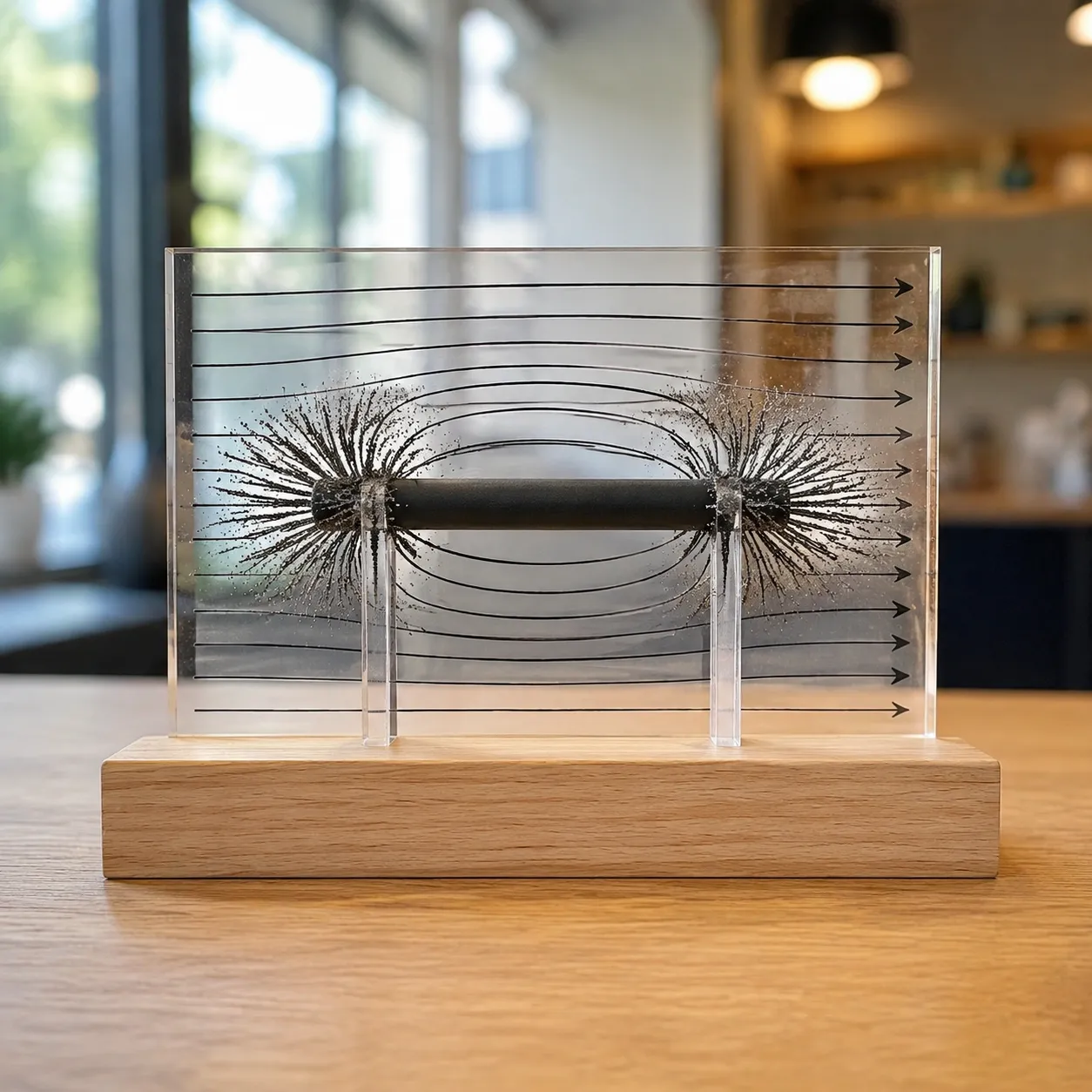
Laminating a core involves stacking thin, electrically insulated sheets of silicon steel together. To understand how magnetic fields are channeled without loss, studying how magnetic rod structures work offers great insight into flux direction. In transformer cores, laminations break up eddy current pathways, concentrating maximum magnetic flux into the secondary winding while preserving system efficiency.
What soft magnetic material is best suited for high-frequency transformer coupling?
Standard silicon steel cores perform well at 50/60 Hz grid frequencies, but high-frequency coupling (kHz to MHz range) requires materials with higher electrical resistivity to prevent severe core losses:
-
- MnZn & NiZn Soft Ferrites: Best for low-cost, high-frequency power supplies and RF transformers due to their near-insulating electrical resistance.
- Nanocrystalline Alloys: Ideal for compact, ultra-high-efficiency designs requiring high saturation flux density and superior magnetic permeability.

 German
  English
  Vietnamese
  Spanish (Mexico)
  Russian
  Turkish
  Polish
  Hindi
Hindi  Thai
Thai  Malay
Malay  Korean
  Japanese
  French
  Czech
Czech  Danish
  Dutch
Dutch  Finnish
  Italian
  Portuguese (Brazil)
  Portuguese (Portugal)
  Slovenian
  Ukrainian
  Hebrew
  Scottish Gaelic
  Hungarian
  Tagalog
  Spanish (Spain)
  Serbian
  Indonesian
  Slovak
  Dutch (Belgium)
  Persian
  Arabic
  Romanian
  Estonian
  Greek
Greek  Bulgarian

[…] Previous Custom Halbach Array Permanent Magnet Manufacturer […]