
What Are Magnetic Field Lines?
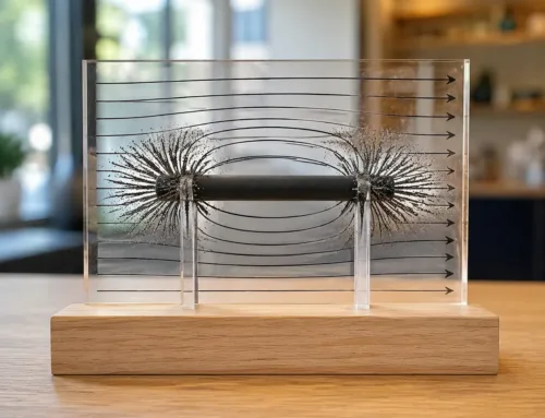
Magnetic field lines, often referred to as magnetic lines of force, are visual models we use to represent the invisible forces surrounding a magnet. While magnetism cannot be seen with the naked eye, these lines map the trajectory and behavior of magnetic vectors across space.
-
- Visual Representation: They illustrate how magnetic force propagates around magnetic objects and electrical currents.
- Vector Indicator: The tangent at any point along a line shows the exact magnetic field direction at that position.
- Force Visualization: Tightly packed lines indicate high magnetic strength, while spread-out lines reveal weaker zones.
Mapping Invisible Magnetic Fields
Because magnetic fields exist continuously in three dimensions, mapping them requires a clear framework. We use imaginary field lines to turn abstract magnetic potential into measurable, predictable patterns.
This mapping framework provides critical data for engineering:
1. Field Orientation: Shows which way a magnetic dipole or test compass will align.
2. Gradient Analysis: Identifies how field intensity drops over distance.
3. Flux Distribution: Helps us design balanced magnetic circuits and efficient electromechanical systems.
Direction of Field Lines: Outside vs. Inside
A fundamental rule of magnetism is that field lines form continuous, unbreakable loops. The direction shifts depending on whether you observe the field outside or inside the magnet:
-
- Outside the Magnet: Field lines emerge from the polo norte and curve through the surrounding space toward the polo sur.
- Inside the Magnet: The lines continue straight through the magnetic material, traveling from the polo sur back to the polo norte.
This seamless loop ensures that magnetic poles always operate in pairs, creating a closed-circuit flow of magnetic flux.
Key Properties of Magnetic Field Lines
To properly analyze magnetic circuits and assemblies, we rely on core geometric rules that define how las líneas del campo magnético behave in space.
Continuous Closed Loops
Magnetic lines of force never start or stop abruptly. Instead, they form continuous, unbroken loops:
Outside the magnet: Lines emerge from the north pole and travel toward the south pole.
Inside the magnet: Lines complete the loop by flowing from the south pole back to the north pole.
Understanding this loop behavior is fundamental when working with standard bar magnet magnetic field distributions.
Field Lines Never Intersect
Lines of force cannot cross or overlap under any condition. At any given point in a magnetic field, the field direction is unique. If two lines were to cross, a compass placed at that intersection would have to point in two directions at the same time, which is physically impossible.
Line Density Measures Field Strength
The spacing between field lines provides an immediate visual measure of la fuerza del campo magnético (magnetic flux density):
High density (crowded lines): Indicates a strong magnetic field, typically found directly at the pole faces.
Low density (spaced lines): Indicates a weaker field as distance from the source increases.
Engineered components like a multipole magnetic ring utilize specific pole spacing to concentrate field line density closely along working surfaces.
Uniform vs. Non-Uniform Field Patterns
Field configurations generally fall into two distinct categories:
-
- Uniform Magnetic Field: The lines are straight, parallel, and evenly spaced. Field strength and direction remain identical throughout the entire zone, such as between two closely spaced opposite flat poles.
- Non-Uniform Magnetic Field: The lines curve, converge, or spread apart. Field strength and direction vary continuously depending on position, which is the typical behavior seen around open single-magnet configurations.
How to Visualize and Trace Magnetic Field Lines
Because magnetic forces are invisible to the naked eye, we rely on practical visual tools and experiments to map out their paths. Whether you are running a classroom demonstration or testing a prototype in a lab, tracing these invisible paths gives us immediate insight into magnetic strength, flux distribution, and polarity.
The Classic Iron Filings Method Step-by-Step
El iron filings experiment remains the most intuitive way to reveal a magnetic field pattern in real time. Iron shavings act like tiny magnetic dipoles, physically aligning along the magnetic lines of force.
Here is how we set it up:
-
- Place the magnet: Lay a magnet flat on a clean, level surface.
- Add a barrier: Place a sheet of white paper, clear acrylic, or cardstock directly over the magnet.
- Sprinkle the filings: Lightly and evenly dust fine iron filings across the sheet from a short height.
- Tap the surface: Gently tap the edge of the sheet. The vibration overcomes surface friction, allowing the filings to align smoothly along the curves of the field.
- Observe the pattern: Notice how the density of filings peaks near the poles, clearly displaying where the field is concentrated.
Using a Plotting Compass to Map Field Directions
While iron filings show shape and density, they do not show polarity direction. A small plotting compass lets us trace the actual vector path from the north pole to the south pole.
-
- Place the magnet on a sheet of grid paper and trace its outline.
- Place the compass near the magnet’s north pole and mark dots where the needle points.
- Move the compass so its tail aligns with the previous dot, mark the new tip position, and repeat.
- Connect the dots to draw a smooth, continuous line showing the exact magnetic field direction.
Digital Field Sensors and Magnetic Viewing Film
For engineering design, quality control, and advanced testing, modern diagnostic tools provide cleaner, non-destructive visualization:
-
- Magnetic Viewing Film: This flexible sheet contains micro-encapsulated nickel flakes suspended in oil. Laying the film over a magnetic assembly reveals pole boundaries, multi-pole patterns, and flux leakage in seconds without messy cleanups.
- Digital Hall Effect Sensors: Electronic Gauss meters and digital probes measure precise magnetic flux density at specific coordinates, turning physical field lines into quantitative 2D or 3D data.
Understanding how these flux paths align is essential when designing high-torque drive systems, such as seeing what is mining magnetic coupling and how it works through non-contact magnetic alignment in industrial machinery.
Magnetic Field Line Patterns in Different Setups
Magnetic field line patterns shift dramatically depending on the source, geometry, and proximity of other magnetic objects. When we map these configurations, we see distinct line distributions that govern how forces interact in real-world systems.
Single Bar Magnet vs. Interacting Magnets
A single bar magnet produces an uncomplicated dipole field where lines exit the north pole, curve outward in broad symmetrical arcs, and enter the south pole. Introducing a second magnet alters this landscape immediately:
-
- Opposite Poles Attracting (North–South): Field lines emerge from the north pole of one magnet and bridge straight across to the south pole of the other, creating a high-density, high-tension magnetic bridge pulling them together.
- Like Poles Repelling (North–North or South–South): Field lines bend sharply away from each other into the surrounding space. They never cross, creating a central dead zone or neutral point where the net magnetic force equals zero.
When working with high-grade materials—such as when analyzing what is the difference between N52 and N55 magnets—the physical geometry stays the same, but the field line density and concentrated holding power increase significantly.
Earth’s Geomagnetic Field and Polar Orientation
Our planet behaves like a colossal tilted bar magnet. The circulating molten iron in Earth’s outer core generates an extensive magnetosphere:
-
- Earth’s geographic North Pole actually hosts a polo magnético sur, which is why the north-seeking needle of a compass points northward.
- Field lines emerge from the southern hemisphere, loop far out into space, and re-enter near the northern polar region.
- Near the equator, Earth’s magnetic field lines run nearly horizontal to the surface; near the poles, they plunge straight down.
Straight Current-Carrying Wire and the Right-Hand Grip Rule
Electric current running through a straight conductor generates circular magnetic field lines around the wire rather than pole-to-pole loops:
-
- Field Pattern: Concentric rings forming unbroken circles centered on the wire.
- Right-Hand Grip Rule: Point your right thumb in the direction of the electric current, and your curled fingers show the exact direction of the circular magnetic field lines.
- Intensity: The circles are packed tightly near the conductor surface and spread wider as distance increases.
Solenoids and Electromagnet Field Distribution
Winding a wire into a tight coil (solenoid) combines the circular field loops of individual turns into a unified magnetic field pattern nearly identical to a bar magnet:
-
- Inside the Coil: The lines run parallel, exceptionally straight, and tightly packed, producing an intensely uniform magnetic field.
- Outside the Coil: The field lines spread out in wide loops from one end of the coil to the other, creating clearly defined north and south magnetic poles.
- Electromagnet Core Boost: Inserting a ferromagnetic iron core inside the solenoid concentrates the magnetic field lines, multiplying the overall magnetic flux density without changing the basic field geometry.
Magnetic Field Pattern Comparison
| Configuración | Field Line Geometry | Peak Field Location | Primary Application |
|---|---|---|---|
| Single Bar Magnet | Symmetrical loops, North to South | Magnetic pole faces | Latches, compass needles, sensors |
| Attracting Magnets | Direct bridging lines between poles | Gap between opposite faces | Clamping assemblies, coupling drives |
| Repelling Magnets | Diverging lines pushed outward | Outer boundaries away from gap | Maglev systems, magnetic bearings |
| Straight Wire | Concentric circles around wire | Wire surface | Signal cables, basic power conductors |
| Solenoid / Electromagnet | Parallel interior lines, external loops | Inside coil core | Relays, actuators, MRI scanners |
Practical Applications of Magnetic Field Lines
Understanding how las líneas del campo magnético behave allows us to design and optimize critical technologies across everyday electronics and heavy industries. By controlling the path and density of these invisible lines of force, we convert energy, protect sensitive components, and capture high-precision data.
How Electric Motors and Generators Harness Field Lines
Motors and generators rely directly on the interaction between magnetic fields and electrical conductors.
Motores Eléctricos: When current passes through wire coils placed within a magnetic field, the interacting las líneas del campo magnético produce a mechanical force (Lorentz force) that turns the rotor.
Generadores: Moving a conductor through a concentrated densidad de flujo magnético cuts across field lines, inducing an electric current through electromagnetic induction.
Efficiency Gains: Shaping the field lines using high-permeability core materials prevents flux leakage, maximizing operational torque and power output.
Magnetic Resonance Imaging (MRI) and Medical Diagnostics
In healthcare, precise control over magnetic lines is essential for non-invasive imaging. High-field MRI scanners use powerful superconducting magnets to align the hydrogen nuclei in the human body along uniform field lines. Specialized gradient coils temporarily alter the local la fuerza del campo magnético to generate detailed 2D and 3D cross-sectional images of soft tissue. You can explore more about these systems in our guide on medical field magnet applications.
Navigation Systems and Compass Calibration
Earth acts as a giant magnetic dipole, and navigation tools depend on reading its field orientation accurately:
Magnetic Compasses: Align parallel to geomagnetic field lines to establish direction relative to magnetic north.
Digital Magnetometers: Modern smartphones, drones, and aircraft use solid-state sensors to measure field line vectors across three axes.
Compass Calibration: Engineers map and counteract local magnetic distortions (hard and soft iron effects) caused by nearby structural metals to maintain accurate directional readings.
Magnetic Shielding and Data Storage Devices
Directing the flow of field lines is just as important as generating them:
Magnetic Shielding: Sensitive electronic components and sensors are enclosed in high-permeability alloys (such as Mu-Metal). These materials redirect las líneas del campo magnético through the shield itself rather than letting them penetrate vulnerable circuitry.
Data Storage Devices: Traditional hard drives and magnetic tape systems utilize micro-scale magnetic write heads. By focusing field lines into tiny, localized spots, they flip the magnetic orientation of microscopic domains on a disk surface to store binary data reliably.
Frequently Asked Questions About Magnetic Field Lines
Do magnetic field lines physically exist or are they just a model?
Magnetic field lines are a visual and mathematical model we use to represent invisible magnetic forces. While the magnetic field itself is a real physical entity that exerts measurable force, the individual lines do not physically exist in space as separate strands. They serve as a practical tool to map out magnetic field direction and intensity.
Why do magnetic field lines form closed loops unlike electric field lines?
Unlike electric fields that start on positive charges and end on negative charges, magnetic monopoles do not exist in nature. Every magnet operates as a dipolo magnético with both los polos norte y sur. Because of this, we observe closed loop field lines that travel continuously from the north pole to the south pole outside the magnet, and return from south to north through the interior. This continuous loop behavior is also fundamental when evaluating how energy transfers in systems using magnetic coupling in transformers.
What happens to field lines when opposite magnetic poles meet?
When opposite poles face each other, the lines of force emerge from the north pole and enter directly into the adjacent south pole. This creates a concentrated magnetic field pattern between the two faces, pulling the magnets together:
-
- Shortest path: The lines contract along their length, generating an attractive mechanical force.
- Higher field density: The concentration of flux lines between the poles leads to localized high la fuerza del campo magnético.
Can magnetic field lines pass through a vacuum and solid materials?
Yes. Magnetic fields do not require a physical medium to propagate; they pass freely through a vacuum, air, water, and non-magnetic solids like wood, plastic, aluminum, and brass. However, ferromagnetic materials like iron, nickel, and specialized electrical steels redirect and concentrate the lines through their structure rather than letting them pass unaltered.
How does temperature affect magnetic field line strength?
Temperature directly impacts atomic alignment within magnetic materials, influencing overall densidad de flujo magnético:
-
- Low temperatures: Thermal agitation decreases, allowing magnetic domains to align better and strengthening the overall field line concentration.
- High temperatures: Increased thermal vibration disrupts domain alignment, reducing field strength.
- Curie point: If heated past a material’s specific Curie temperature, the permanent magnetic order is lost entirely, causing the external field lines to collapse. Engineers carefully analyze these thermal limits when calculating the strength of a Halbach array magnet field for high-temperature motor and sensor applications.


 Spanish (Spain)
  English
  German
  Vietnamese
  Spanish (Mexico)
  Russian
  Turkish
  Polish
  Hindi
Hindi  Thai
Thai  Malay
Malay  Korean
  Japanese
  French
  Czech
Czech  Danish
  Dutch
Dutch  Finnish
  Italian
  Portuguese (Brazil)
  Portuguese (Portugal)
  Slovenian
  Ukrainian
  Hebrew
  Scottish Gaelic
  Hungarian
  Tagalog
  Serbian
  Indonesian
  Slovak
  Dutch (Belgium)
  Persian
  Arabic
  Romanian
  Estonian
  Greek
Greek  Bulgarian



Deja un comentario