
Why Geometric Dimensioning and Tolerancing Matters for Magnetic Assemblies
In my experience, many engineers treat magnets like standard steel components, but that is a costly mistake. Geometric Dimensioning and Tolerancing (GD&T) is the bridge between a magnet that simply “fits” and one that performs. For magnetic assemblies, the stakes are higher because we aren’t just managing physical space—we are managing the air gap.
Mechanical Integrity vs. Magnetic Performance
The relationship between physical dimensions and magnetic output is inseparable. A slight shift in positional tolerance can lead to uneven flux distribution or catastrophic mechanical failure.
- The Air Gap Factor: Magnetic force is inversely proportional to the square of the distance. A variation of just 0.05mm in your Datum Reference Frame (DRF) can result in a 10-15% loss in performance.
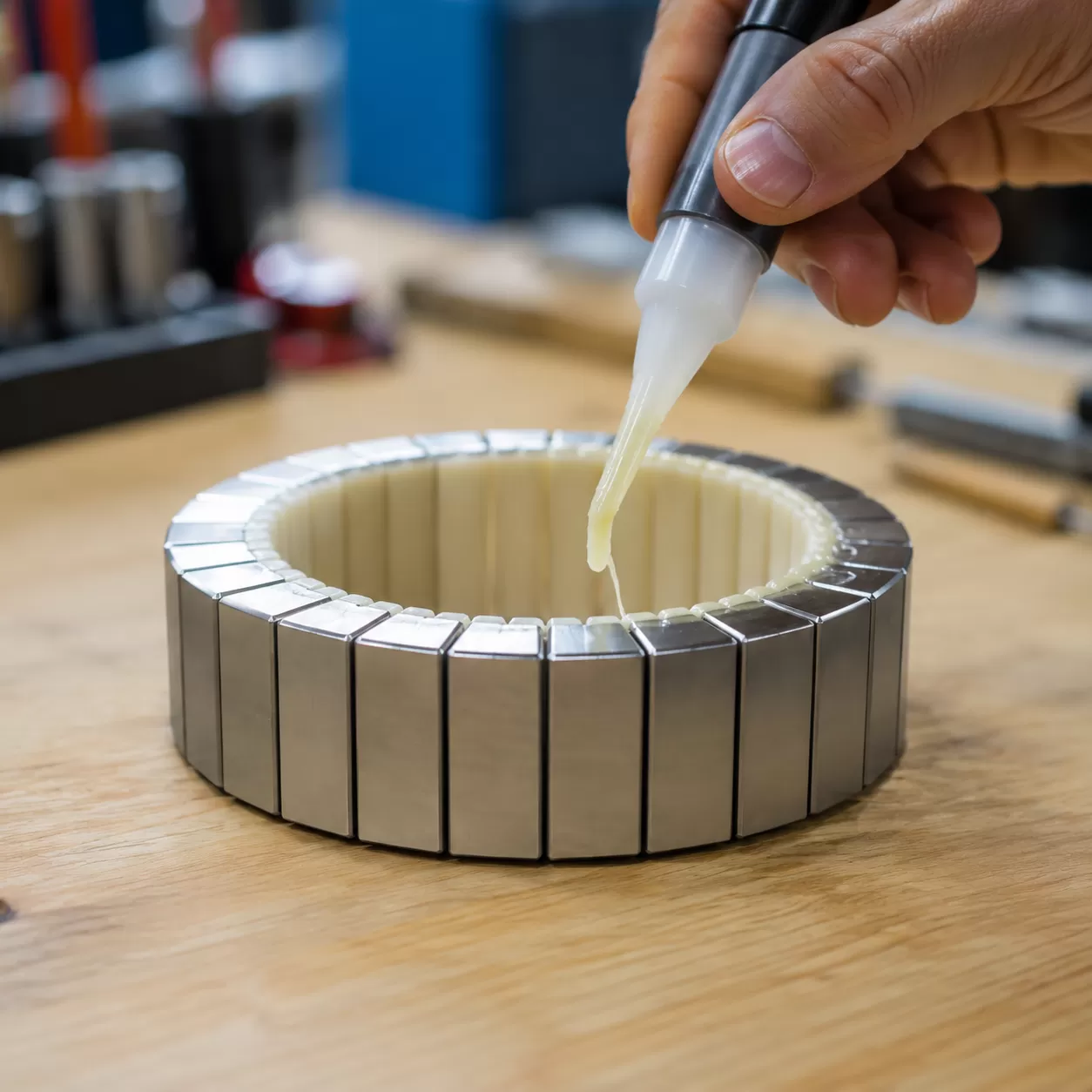
- Structural Risks: Sintered Neodymium is notoriously brittle. Using GD&T helps us define “floating” tolerances that prevent stress concentrations, ensuring the magnet doesn’t crack during press-fit operations.
The Cost of Over-Specifying Precision
I often see prints where every dimension is held to a micron-level precision. While we can achieve this, over-specifying without a clear functional reason drives up scrap rates and production time.
| Spec Type | Impact on Performance | Manufacturing Cost |
|---|---|---|
| Loose Tolerances | High flux leakage, vibration | Matala |
| Over-Specified | Diminishing returns on flux | Exponentially High |
| Optimized GD&T | Peak efficiency, stable air gap | Balanced/Scalable |
By utilizing Maximum Material Condition (MMC), we provide the manufacturing floor with “bonus tolerance,” reducing costs while maintaining the functional requirements of the assembly.
Interchangeability in High-Volume Automated Assemblies
For global markets, interchangeability is non-negotiable. In high-volume automated lines, there is no room for “hand-fitting” parts.
- Alignment: Proper Flatness and Parallelism specs ensure that magnets sit perfectly flush against backplates, crucial for sensor accuracy and motor efficiency.
- Consistency: Adhering to the ASME Y14.5 Standard ensures that a magnet produced in our facility fits perfectly into an assembly line on the other side of the world.
- Tehokkuus: We use GD&T to define the boundaries where robots can reliably pick and place magnets without damaging the edges or losing alignment.
Key Symbols in Magnet Geometric Dimensioning and Tolerancing
In my experience, applying the ASME Y14.5 Standard correctly is what separates a functional magnetic assembly from a pile of scrap. When we look at Magnet Geometric dimensioning and tolerancing, we aren’t just checking if a part is “round” or “flat”—we are ensuring the magnetic field behaves exactly as the simulation predicted.
Form Controls: Flatness and Cylindricity
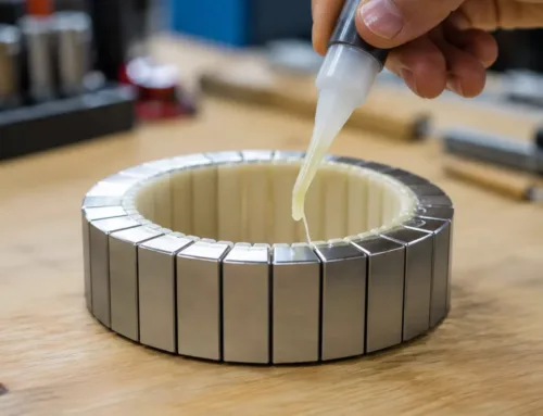
I always emphasize Flatness for magnets that require surface bonding. If the surface isn’t flat, you get uneven adhesive layers, which leads to unpredictable air gaps and reduced magnetic pull. For cylindrical magnets used in rotors, Cylindricity is non-negotiable to ensure a uniform air gap between the magnet and the stator.
Orientation and Location: Why Position is King
While Flatness and Parallelism are important for mechanical fit, Positional Tolerance is the most critical factor in modern sensor and motor applications. If the magnet’s physical center is offset from its Datum Reference Frame (DRF), the magnetic flux center will also be skewed.
- Parallelism: Critical for maintaining a consistent magnetic flux path across two opposing surfaces.
- Perpendicularity: Ensures the magnet sits square in its housing, preventing “cocking” during automated assembly.
- Position: I consider this “King” because it controls the location of the magnet relative to the rest of the assembly, directly impacting torque ripple and sensor accuracy.
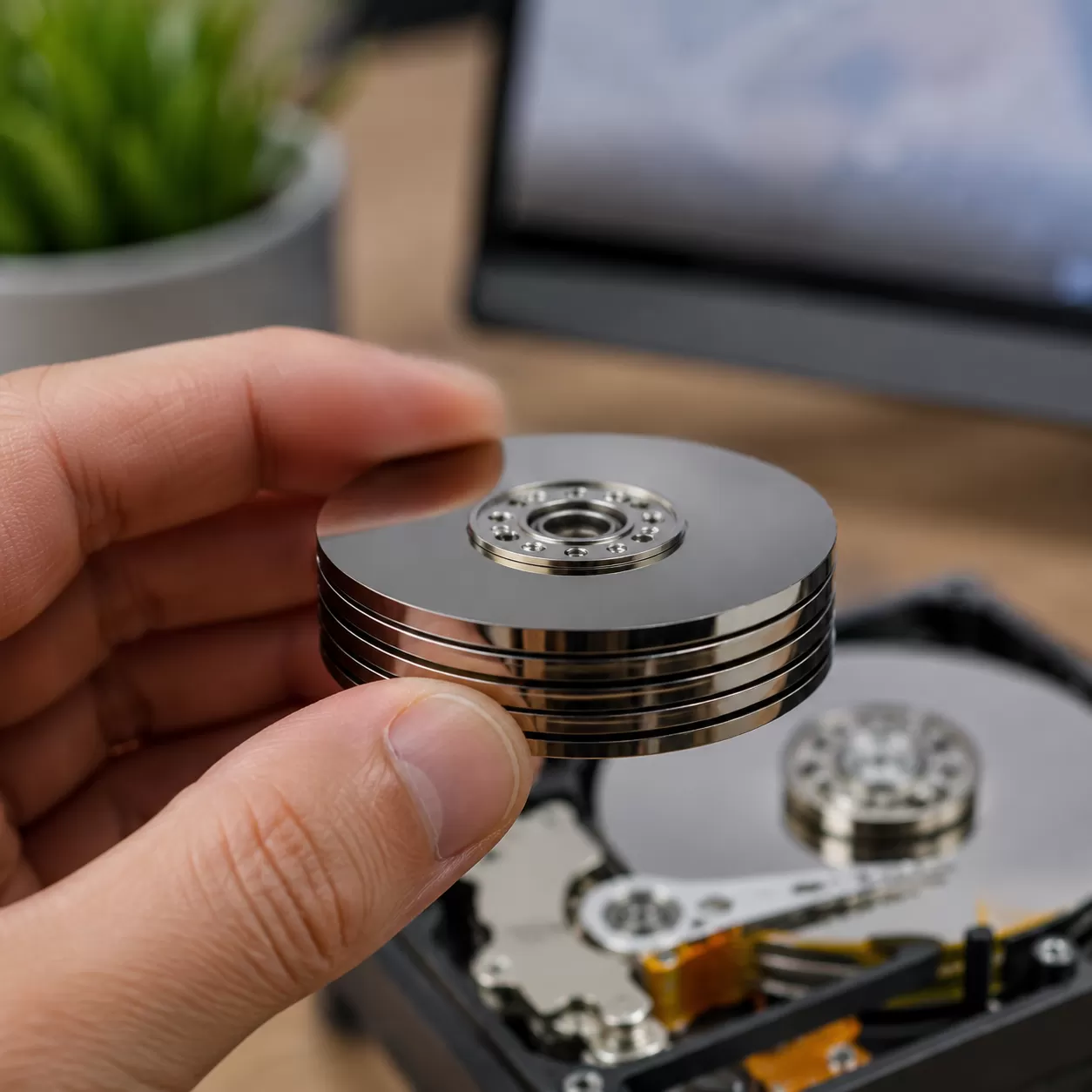
Managing Runout in Rotating Assemblies
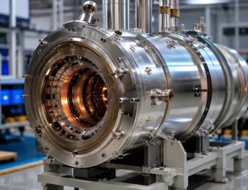
For high-speed applications, we focus heavily on Circular and Total Runout. These controls manage the eccentricity of the magnet relative to the shaft axis. Excessive runout leads to high-frequency vibration and premature bearing failure. I recommend reviewing our bonded magnet data sheet to see how these geometric specifications align with material performance.
| GD&T Symbol | Control Category | Impact on Magnetic Performance |
|---|---|---|
| Flatness | Form | Minimizes air gaps and improves bonding integrity. |
| Parallelism | Orientation | Ensures a uniform magnetic field across the air gap. |
| Position | Location | Crucial for aligning the magnetic pole with the sensor axis. |
| Total Runout | Runout | Reduces mechanical imbalance and noise in motors. |
We often use Maximum Material Condition (MMC) to allow for greater manufacturing flexibility without sacrificing the functional requirements of the assembly. By integrating these symbols into your technical print specification, we can achieve Micron-level Precision that ensures every part is interchangeable in high-volume production lines.
Brittle Materials and Magnet Geometric Dimensioning and Tolerancing Challenges
Applying Magnet Geometric Dimensioning and Tolerancing is a different beast when you aren’t working with ductile metals. In our experience, the brittle nature of Sintered Neodymium (NdFeB) ja Samarium-koboltti (SmCo) creates unique roadblocks that the standard ASME Y14.5 Standard doesn’t always account for in a vacuum.
Material Constraints of NdFeB and SmCo
Unlike steel, these materials don’t deform—they fracture. This makes brittle material machining a high-stakes game. When we specify tight flatness and parallelism, we have to account for the internal stresses of the sintering process.
- Sintered Neodymium (NdFeB): Highly prone to oxidation; often requires a protective magnet coating that adds its own layer of dimensional complexity.
- Samariumkobaltti (SmCo): Even more brittle than Neo, making it extremely sensitive to edge chipping during grinding.
Managing the “Chipper Factor”
In the magnet world, the “chipper factor” is a reality of life. Small chips on the edges of a sintered block can lead to false failures during inspection if the Datum Reference Frame (DRF) isn’t established correctly. We focus on:
- Radiused Edges: Minimizing sharp corners to prevent crack initiation.
- Surface Profile: Using profile tolerances rather than simple linear dimensions to manage irregular geometries.
- Functional Gauging: Ensuring the part fits the assembly even if minor cosmetic chipping exists.
Overcoming Measurement Obstacles
Standard metrology often fails when faced with magnetic interference. Conventional CMM (Coordinate Measuring Machine) probes can be pulled or deflected by the magnetic field, leading to “ghost” errors in positional tolerance.
| Challenge | Impact on GD&T | Mitigation Strategy |
|---|---|---|
| Magnetic Pull | Deflects physical probes | Use non-magnetic (ruby/ceramic) tips or optical scanners. |
| Flux Leakage | Distorts electronic sensors | Shielding or increasing standoff distance during inspection. |
| Material Hardness | Rapid tool wear | Micron-level precision grinding with diamond-tipped tooling. |
We integrate advanced material science into our quality checks to ensure that magnetic flux leakage doesn’t compromise the accuracy of your technical print specification. By anticipating these physical hurdles early, we keep your production on track without the headache of constant rejections.
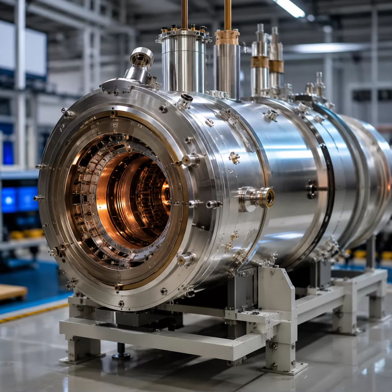
Precision Production and Geometric Dimensioning and Tolerancing Capabilities at NBAEM
At NBAEM, we turn complex blueprints into high-performance reality. Our production floor is designed specifically to handle the rigors of Magnet Geometric dimensioning and tolerancing, ensuring that the physical shape of the magnet never compromises its magnetic circuit.
Precision Grinding and AI Inspection
We utilize advanced precision grinding techniques to achieve micron-level tolerances on even the most brittle materials. Because traditional manual checks can’t always catch subtle deviations in Sintered Neodymium (NdFeB), we have integrated automated AI-driven inspection systems. These high-speed sensors verify positional tolerance and surface profile in real-time, providing 100% data transparency for every batch.
Technical Specifications and Quality Standards
We integrate material science with geometric accuracy to ensure your magnets perform exactly as modeled. This involves balancing the physical dimensions with the BH curve to prevent flux leakage or mechanical failure. As a leading neodymium magnet supplier, we maintain the highest global quality benchmarks:
| Capability | Standard Specification |
|---|---|
| Machining Accuracy | Micron-level precision (down to ±0.005mm) |
| Inspection Logic | Automated AI Vision & CMM Analysis |
| Quality Compliance | IATF 16949 Certified |
| Dokumentaatio | Full PPAP-taso 3 Tuki |
Our commitment to IATF 16949 ja PPAP-taso 3 means every part we ship is backed by rigorous data. We don’t just make magnets; we provide engineered components that fit perfectly into your high-volume automated assemblies without the need for manual sorting or rework.
Designing for Success with Magnet Geometric Dimensioning and Tolerancing
Getting us involved early in the design phase is the single best way to ensure your project stays on track. When we review your Magnet Geometric dimensioning and tolerancing requirements at the start, we can spot potential manufacturing hurdles before they become expensive mistakes. We help you balance the need for Micron-level Precision with the physical realities of working with brittle materials like Sintered Neodymium (NdFeB).
By referencing our samarium cobalt magnet data sheet, engineers can better understand the baseline performance and mechanical limits that drive specific Technical Print Specifications. Using the right magnetic GD&T reference tools ensures that your Datum Reference Frame (DRF) is functional, not just theoretical.
Engineering Checklist for Magnet Prints
To ensure a smooth transition from design to production, every magnet print should include:
- Material Grade: Specific chemistry and magnetic properties.
- Magnetic Axis: Clear indication of the direction of orientation.
- Geometric Controls: Essential Positional Tolerance ja Surface Profile requirements.
- Päällysteen Paksuus: Account for plating dimensions in your final tolerance stack.
- Inspection Points: Defined areas for flux density or pull force testing.
Magnetic Geometric Dimensioning and Tolerancing FAQ
| Kysymys | Vastaus |
|---|---|
| What is the tightest tolerance for a sintered magnet? | For critical features, we can achieve tolerances as tight as ±0.005mm through precision grinding, though standard high-precision runs typically target ±0.01mm to ±0.05mm. |
| How does GD&T affect magnetic flux leakage? | Huono Parallelism ja Perpendicularity can cause the magnetic axis to tilt. This misalignment leads to unintended magnetic flux leakage, which can interfere with nearby sensors or reduce motor efficiency. |
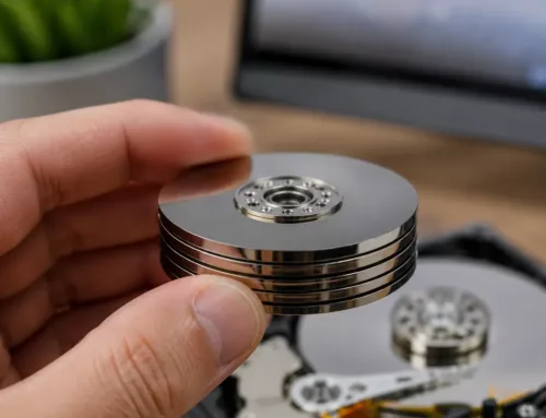
If you are working on complex motor designs, our high-performance laminated magnets often require even stricter geometric controls to minimize eddy current losses while maintaining structural integrity. Focusing on the right Magnet Geometric dimensioning and tolerancing early on ensures that your assembly performs exactly as simulated, without the “hidden costs” of over-specification or assembly failures.

Jätä kommentti