
Хочете максимізувати щільність крутного моменту, зменшити вагу компонента або викорінити небажані паразитні поля у своїх електромагнітних конструкціях? Стандартні магнітні розташування часто не витримують вимог, коли ваша програма потребує пікової ефективності поля.
Опанування конфігурації магнітної масиву Халбаха змінює правила гри. Обертаючи просторово вектор магнітизації, цей дизайн подвоює значень магнітної щільності потоку на одному активному боці, одночасно фактично скасовуючи його на протилежному — забезпечуючи максимальну концентрацію поля без збільшення ваги або потреби в активному живленні.
У цьому посібнику ви дізнаєтесь, як вибирати та оптимізувати правильні розташування — від плоских масивів to циліндричних масивів Халбаха, порівнюючи 4-патерн (90°) та 8-патерн (45°) кроки обертання для підвищення ефективності у високопродуктивних моторах, маглев-системах та спеціалізованих промислових пристроях.
Давайте відразу розпочнемо.
Що таке конфігурація магнітного масиву Халбаха?
Ми визначаємо конфігурації магнітної масиву Халбаха як спеціалізований устрій постійних магнітів, який концентрує магнітний потік з одного боку, знижуючи його майже до нуля з іншого. Обертаючи напрямок намагнічування сусідніх магнітів, ми створюємо самозахищену, односторонню модель магнітного потоку без потреби важких залізних опорних plates.
Розуміння обертання магнітного поля на 90 градусів
У стандартних компоновках магнітів магнітні поля радіально зійшуються від північного до південного полюсу. У наших конфігураціях Халбаха ми зміщуємо орієнтацію магнітного поля на 90 градусів послідовно через суміжні блоки (0°, 90°, 180°, 270°).
-
- Векторне обертання: Магнітний вектор обертається безперервно через послідовність у масиві постійних магнітів.
- Конструктивне поєднання: Магнітні поля додаються разом на активній робочій поверхні.
- Руйнівне скасування: Протилежні магнітні поля взаємно нейтралізуються на протилежному неробочому боці.
Стандартні конфігурації магнітів проти конфігурацій Халбаха
| Особливість | Стандартний масив магнітів | Конфігурація магніту з масиву Халбаха |
|---|---|---|
| Розподіл флюксу | Симетричний (рівний флюкс з обох сторін) | Асиметричний (Флюкс-магніт з однієї сторони ефект) |
| Сила поля | Стандартна щільність флюксу | До подвоєна щільність флюксу на сильній стороні |
| Захист зворотного заліза | Потребує важких стельових(стилових) ярмі | Мінімальна або відсутня потреба у додаткових важких ярмах |
| Ефективність щодо ваги | Нижчий коефіцієнт сила-медз ваги | Максимальний коефіцієнт сила-медз ваги |
Практичні інженерні переваги одностороннього потоку
-
- Різке зниження ваги: усунення громіздких стальних опорних вилка зменшує загальну вагу системи.
- Запобігання сторонньому полю: вбудована ефективність магнітного екранування захищає сусідні електронні компоненти від магнітних завад.
- Максимальна магнітна продуктивність: направлення всього доступного магнітного потоку до робочої сторони забезпечує максимальну густину сили на одиницю об'єму.
Як працює масив Халбаха?
Коли ми розглядаємо конфігурацію магнітів масиву халбаха, секрет його продуктивності полягає у маніпуляціях просторовим вектором. Замість того, щоб вирівнювати магніти так, щоб усі полюси північ facing однаковим напрямком, ми обертаємо обертання магнітного диполя послідовно на 90 градусів через кожний сусідній блок у постійних магнітів.
Математичний принцип векторного сумування магнітних полів
Основний механізм покладається на додавання магнітних векторів. Оскільки магнітний потік проходить між сусідніми magnets, систематично змінюючи орієнтацію магнітного поля змінює те, як перекриваються фізичні поля:
-
- Конструктивне суперпозиція: Вектори потоків зливаються в одному напрямку на активному боці, щоб підвищити потужність.
- Заблукана інтерференція: Протилежні вектори поглинають лінії поля на неактивному боці.
Розуміння шляхів векторів є необхідним для високопродуктивних збірок. Ви можете побачити аналогічну структурну динаміку магніту в дії, розглянувши як працюють збірки магнітних стрижнів у практичних застосуваннях флукс-каналізації.
Скасування полів на слабкому боці
Застосовуючи безперервний зсув векторів на 90 градусів, лінії флуксу на задній поверхні повертаються до сусідніх магнітів перед тим, як розширитися назовні.
-
- Ледь помітне відтікання поля: Знищення інтерференцією зменшує сторонні магнітні поля на задній поверхні майже до нульового рівня.
- Переваги самозахисту: Максимізує ефективність магнітного екранування без потреби у важких сталевих зворотних плитах або залізному якку, різко знижуючи загальну масу системи.
Підвищення сили поля з боку сильного
На активній стороні горизонтальні та вертикальні вектори поєднуються конструктивно. Це створює справжній односторонній потоковий магніт з винятковими зростаннями щільності потоку:
| Магнітний Характеристика | Стандартне розташування магніту | Конфігурація магніту Halbach Array |
|---|---|---|
| Розподіл поля | Симетричний (верхній 50% / нижній 50%) | Асиметричний (~90%+ на активній стороні) |
| Відносна сила потоку | Базовий рівень (1.0x) | До 1.4x сильніший на сильному боці |
| Захист зворотного заліза | Потрібно (додає вагу) | Непотрібний (вбудоване скасування) |
Ми досягаємо максимуму магнітне фокусування потоку саме там, де потрібно, забезпечуючи вищу щільність потоку без додавання зайвої ваги.
Ключові типи конфігурацій магнітної масиву Halbach
Ми групуємо кожен конфігурацію магнітів масиву халбаха на три основні структурні комплекти залежно від того, чи має потік пройти по плоскому поверхні, всередині циліндра чи навколо обертового валу.
Лінійний масив Halbach
A лінійний масив Halbach розміщує постійні магніти поруч один з одним на плоскому шарі.
-
- Магнітна орієнтація: Обертає вектор поля на 90 градусів від кожного сусіднього магнітного блоку.
- Поведе потік так: Створює потужну односторонню магнітну поверхню, водночас практично замикаючи зворотню сторону.
- Головне використання: Левітація маглев-потяга, високошвидкісні лінійні двигуни та прецизійні позиційні стійки.
- Ключова перевага: Забезпечує максимальну утримуючу та рушійну силу без потреби у важкому екрануванні з заднім залізом.
Щоб зрозуміти, як ці обернені вектори сумуються математично, розгляньте як працюють магніти з масивом Халбаха у реальних системах лінійного руху.
Круглий масив Халбаха та циліндри Халбаха
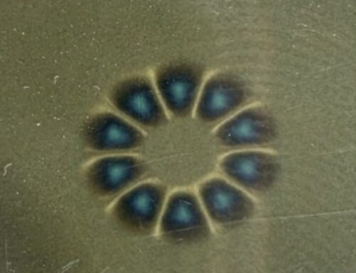
Згинання плоскої послідовності у безперервне кільце утворює кулевим Халбаховим циліндром.
-
- Внутрішнє фокусування потоку: Зосереджує надзвичайно однорідне магнітне поле строго всередині порожнини циліндра, повністю скасовуючи зовнішнє поле.
- Зовнішнє фокусування потоку: Направляє поле назовні, одночасно захищаючи внутрішню порожнину.
- Головне використання: Магнітне резонансне обладнання, прискорювачі частинок та безконтактні магнітні з'єднання.
Халбахові ротори у моторах і генераторах
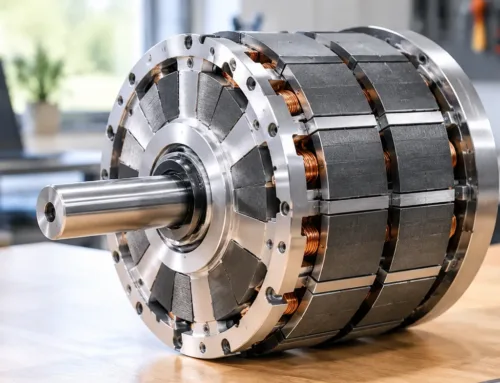
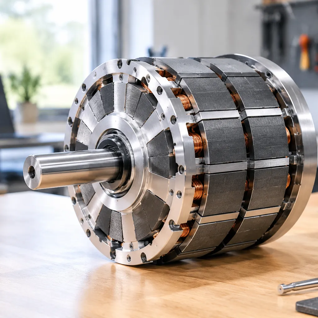
Застосування цього компоновки до щітковий мотор з халбаховим ротором переробляє дизайн приводу високої продуктивності.
-
- Синусоидальне хвильове зображення: Жвавить чистий розподіл магнітного поля, що радикально зменшує зубчастий момент та вібрацію двигуна.
- Збільшена щільність моменту: Дає значно вищу щільність флуктуєйла повітряної щілини порівняно зі стандартними радіальними розміщеннями магнітів.
- Головне використання: Приводи двигунів для електромобілів, пропульсія дронів та космічні приводи.
Під час вибору блоків рідкоземельних для високошвидкісних двигунів, вибір які матеріали для magnetів найкращі для масивів Халбаха забезпечує стабільність до високих робочих температур та ризиків демагнітизації.
Швидке порівняння конфігурацій Halbach
| Тип конфігурації | Область фокусування поля | Ключова перевага | Типові застосування |
|---|---|---|---|
| Лінійний масив | Одна плоска поверхня | Прибрає вагу зворотного заліза | Маглев траси, лінійні приводи |
| Халбахова циліндр | Зосереджена внутрішня або зовнішня діаметрова ділянка | Нуль зовнішнього витоку магнітного потоку | Прилади МРТ, фокусування пучка |
| Халбаховий ротор | Окружність повітряного зазору | Низьке змагнення, максимальний крутний момент | BLDC-двигуни, Propulsion для електромобілів |
Як спроектувати та зібрати Halbach-макет магнітів
Будівництво ефективного конфігурацію магнітів масиву халбаха зrequires точний вибір матеріалу, суворе angular-неузгодження та спеціалізоване пристосування. Ми розкладаємо основні інженерні кроки для побудови надійного, високопотокового масиву.
Вибір степеней неодимових магнітів
Вибір правильного класу балансує силу поля, температурні обмеження та механічну міцність протягом збірка неодимового магніту:
-
- Класи N35 до N42: Відмінний вибір для проєктів з суворою економією або застосунків, що працюють при вищих температурних режимах.
- Класи N45 до N52: Забезпечує пікову магнітне фокусування потоку для компактних просторів. Майте на увазі, що вищі класи, такі як N52, є більш крихкими та чутливими до ударів під час встановлення.
Обчислення кутів орієнтації магніту
Щоб побудувати функціональну лінійний масив Halbach опорну або циліндричну компоновку, сусідні магніти повинні дотримуватися суворої послідовності повороту магнітного поля на 90 градусів:
-
- Блок 0°: вектор намагнічування спрямований прямо вгору до активної робочої поверхні.
- Блок 90°: Вектор повернено горизонтально вправо.
- Блок 180°: Вектор спрямований прямо вниз від активної поверхні.
- 270° Блок: Вектор обернуто горизонтально вліво.
Ця повторюваність обертання магнітного диполя прикріплює магнітне поле до робочого боку, водночас зменшуючи поток на не робочій зворотній поверхні.
Керування відштовхувальними силами та структурне зажимання
Зведення протилежних магнітів разом створює екстремальне зсувне та відштовхувальне напруження під час встановлення.
-
- Збірні пристрої: Ми використуємо немагнітні пристрої для вирівнювання — зазвичай виготовлені з високоточного алюмінію 6061 або латуні — щоб послідовно притиснути кожний блок на позицію.
- Механічне зажимання: Магнітна сила з часом погіршуватиме з'єднання, закріплені клеєм, під термічними циклами. Ми посилюємо масиви за допомогою стрічок з нержавіючої сталі, оболонок з вуглецевого волокна або структурних корпусів, подібно до безконтактних приводів торку, що використовуються в системах магнітного зчеплення лише в добувній промисловості.
Рекомендовані варіанти корпусу та клею
| Компонент | Рекомендований матеріал | Функція |
|---|---|---|
| Клей | Двокомпонентний структурний акрил або високошвидкісний епоксид | Утримує блоки від постійного чи опірного поперечного зсуву |
| Корпус | Алюміній, 316-лон Stainless steel, PEEK | Неелектромагнітні матеріали запобігають магнітному замиканню |
| Інкапсуляція | Вакуумно залитий епоксид або обгортка з вуглецевого волокна | Ущільнює блоки неодимію від окиснення та механічного удару |
Реальні застосування масивів Halbach-магнітів
Ми розробляємо збірки постійних магнітів для забезпечення максимальної щільності потоку там, де простір і вага суворо обмежені. Унікальне поворот поля з конфігурацію магнітів масиву халбаха робить його основним вибором у багатьох високотехнологічних галузях світу.
Електричні транспортні засоби та двигуни
У сучасній електромобільності густина потужності має вирішальне значення. Ми інтегруємо ці спеціалізовані конфігурації в тягові двигуни EV високої продуктивності для оптимізації експлуатаційних характеристик.
Вища ефективність: Концентрує потік безпосередньо до статора, зменшуючи енергетичні втрати.
Зменшення ваги: Прибирає важкі залізні підпори, подовжуючи загальний запас ходу.
Плавне прискорення: Інтеграція щітковий мотор з халбаховим ротором зменшує кочення зчеплення для плавного передавання потужності.
Поїзди на маглеві та системи транспорту
Системи високошвидкісних поїздів залежать від спеціалізованих маглевових магнітових конфігурацій для надійного піднесення та навігації.
Пасивне піднесення: Шляхи, що використовують лінійні розташування, створюють гігантські підйомні сили зі збільшенням швидкості транспортного засобу.
Точне керування: Підтримує вирівнювання поїзда вздовж керівної траєкторії без механічного контакту.
Прискорювачі частинок та медичні пристрої
Передова наукова апаратура вимагає інтенсивних, дуже однорідних магнітних полів.
Направлення променя: Приймають частинки в прискорювачах за допомогою кругових розташувань для фокусування заряджених променів з екстремальною точністю.
Компактні МРТ-апарати: Генерує сильні, однорідні поля, необхідні для портативних медичних пристроїв нового покоління.
Споживча електроніка та промислові затискачі
Коли має значення простороморозташування, використання односторонній потоковий магніт макета забезпечує максимальну тримальну силу в тонких профілях продукту.
Пристрої для кріплення: Гарантує чисте кріплення аксесуарів до планшета з защіпочками та модульного обладнання.
Точне обладнання: Забезпечує надзвичайно сильні магнітні затискачі дверей та спеціалізовані кріплення що тримають магнітні поля ізольованими, не заважаючи чутливим електронним пристроям поруч.
Плюси та мінуси магнітної конфігурації масиву Халбаха
Ми регулярно оцінюємо конфігурацію магнітів масиву халбаха щоб збалансувати максимальну інтенсивність магнітного поля із складністю виробництва для компактних апаратних застосунків.
Ключові переваги
-
- Максимізована густота магнітного потоку: Зосередження ліній поля на одну робочу поверхню майже подвоює магнітне фокусування потоку без додавання фізичного об’єму.
- Зменшення ваги та вбудований самозахист: Майже повне скасування поля з слабого боку забезпечує високу ефективність магнітного екранування, дозволяючи позбутися важких зворотних жалюзі з заліза.
- Висока просторовий ефективність: Вихід пікового поля у тісних зазорах дозволяє легші, більш потужні приводи та актуатори.
Ключові недоліки
-
- Збірка піддає ризику та складність: Примусове відштовхування магнітних векторів у цільові оберти вимагає спеціалізованих пристроїв для вирівнювання та високу міцність з’єднання.
- Чутливість до температури: Як і більшість високопродуктивних наборів неодимових магнітів, підвищені робочі температури можуть призвести до демагнетизації, якщо теплові ліміти перевищено.
- Вищі витрати на виробництво: Прецизійне багатокутне вирівнювання магнітів збільшує кількість виробничих операцій порівняно з звичайним постійних магнітів.
Порівняння компромісів
| Показник продуктивності | Конфігурація магніту Halbach Array | Стандартне розташування магніту |
|---|---|---|
| Щільність потоку робочого боку | Сконцентрований (до 2x) | Симетричний (рівний з обох сторін) |
| Потрібне зовнішнє захистування | Мінімальний (Самозахист) | Високий (потребує залізної підкладки) |
| Складність збірки | Високий (Потрібні спеціальні пристрої) | Низький до помірного |
| Загальна маса системи | Легкий | Важкий |
| Витрати на виробництво | Вищий | Стандарт |
Часто задавані питання про масиви Халбаха
Наскільки сильніше масив Халбаха порівняно з обычним розташуванням магнітів?
Коректно підібраний конфігурацію магнітів масиву халбаха збільшує щільність магнітного потоку на 1.4× до 2× (підсилення з 40% до 100%) на активній стороні порівняно з стандартним чергуючим масивом постійних магнітів з однаковою вагою. Обертаючи вектор поля, ми концентруємо майже всю корисну магнітну енергію на одну робочу поверхню. Щоб переглянути фізичну векторну математику за цим перерозподілом потоку, ознайомтесь з як працюють магніти з масивом Халбаха у реальних системах.
Чи можете ви збудувати масив Halbach із використанням стандартних прямокутних магнітів?
Так. Ви не потребуєте виготовлення спеціально формованих зігнутих магнітів для створення функціональних масивів. Стандартні прямокутні блоки із стандартного збірка неодимового магніту працюють надійно.
-
- Обертання на 90 градусів: Розмістіть сусідні прямокутні блоки так, щоб їх вектори магнітизації поверталися на кроки 90 градусів (0°, 90°, 180°, 270°).
- Перенаправлення потоків: Ця проста компоновка створює ефективний односторонній потоковий магніт без дорогого інструмента під замовлення.
- Вимога зажиму: Оскільки сусідні магніти штовхають бічно один проти одного під час встановлення, потрібні міцні механічні зажимні пристрої.
Чи потребують масиви Halbach зовнішнього залізного кожухового захисту?
Зазвичай ні. Головна перевага вибору лінійний масив Халбаха or ротор Халбаха вбудоване самозахистне екранування.
-
- Скасування поля: магнітне поле на не робочій стороні природно знижується майже до нульових рівнів.
- Збереження ваги: видалення важких задніх пластин з заліза істотно знижує загальну масу системи, роблячи ці масиви ідеальними для мобільних та авіакосмічних застосувань. Дізнайтеся більше про де використовуються магніти масиву Халбаха у галузях, чутливих до ваги.
- Особливі випадки: Тонке залізне зворотне покриття додається лише тоді, коли корпус містить чутливу до управління електроніку безпосередньо позаду слабкої сторони.
У чому різниця між 1D і 2D масивом Халбаха?
| Особливість | 1D масив Халбаха | 2D масив Халбаха |
|---|---|---|
| Магнітна вісь обертання | Обертається вздовж однієї лінійної або колової траєкторії | Обертається водночас вздовж осей сітки X та Y |
| Розподіл флюксу | Направляє потік на одну двовимірну площину | Формує високо зосереджену, локалізовану тривимірну сітку поля |
| Загальні застосування | Маглев-доріжка для напрямних, лінійні приводі, безщіткові мотори | Багатосекційні плоскі платформи, таблички левітації, прецизійна оптика |
| Складність збірки | Помірно (потрібне односекційне стискання) | Високий (потрібне багодоповідне утримання сили) |

 Ukrainian
  English
  German
  Vietnamese
  Spanish (Mexico)
  Russian
  Turkish
  Polish
  Hindi
Hindi  Thai
Thai  Malay
Malay  Korean
  Japanese
  French
  Czech
Czech  Danish
  Dutch
Dutch  Finnish
  Italian
  Portuguese (Brazil)
  Portuguese (Portugal)
  Slovenian
  Hebrew
  Scottish Gaelic
  Hungarian
  Tagalog
  Spanish (Spain)
  Serbian
  Indonesian
  Slovak
  Dutch (Belgium)
  Persian
  Arabic
  Romanian
  Estonian
  Greek
Greek  Bulgarian

Залишити коментар