
Frameless Torque Motor Anatomy and Operating Principles
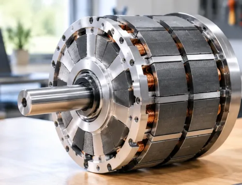
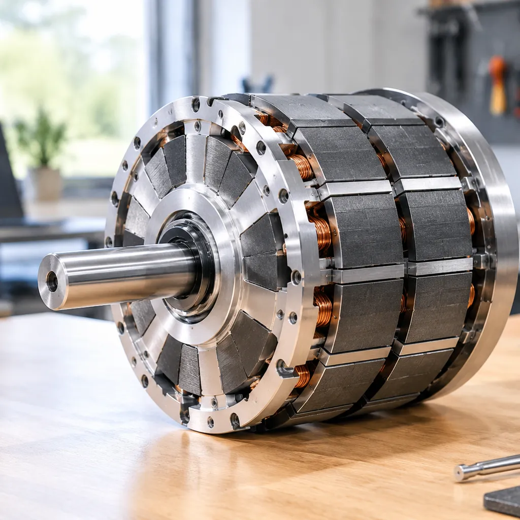
A frameless torque motor delivers high-density electromagnetic force directly to your mechanical load. By stripping away traditional motor frames, shaft extensions, and end-bells, we provide an unhoused stator and rotor assembly that mounts directly inside your machine housing. Operating as a direct-drive permanent magnet synchronous motor (PMSM), it converts electrical energy into precise rotary force with zero mechanical compliance.
[ Machine Housing / Host Structure ]
+———————————————–+
| Stator Core Laminations & Copper Windings |
| [ Air Gap: 0.3 mm – 1.0 mm ] |
| Rotor Ring with Neodymium / SmCo Magnets |
+———————————————–+
[ Large Hollow Bore / Optical Clearance ]
Stator Core Lamination, Copper Slot Fill Factor, and Insulation Classes
The stator is the stationary electromagnetic engine of the kit. We optimize its efficiency through precise lamination and winding architectures:
-
- Silicon Steel Laminations: We use ultra-thin (0.1 mm to 0.35 mm) electrical steel laminations stacked under precise pressure to minimize hysteresis and eddy-current losses at elevated commutation frequencies.
- Copper Slot Fill Factor: Through precision needle-winding and segmented stator teeth, we push the copper slot fill factor beyond 55% to 60%. Higher copper volume lowers electrical resistance ($R$), directly reducing $I^2R$ thermal dissipation and maximizing continuous torque density.
- High-Temperature Insulation: Our stators utilize Class H (180°C) or Class 200 (200°C) insulation systems with vacuum pressure impregnation (VPI), protecting internal windings against dielectric breakdown, moisture, and thermal cycling stress.
Slotted vs. Slotless Stator Design
Choosing between slotted and slotless configurations dictates system smoothness and peak output:
| Feart | Slotted Stator Design | Slotless Stator Design |
|---|---|---|
| Torque Output | Maximum torque density via concentrated iron teeth flux paths | Moderate torque density; requires larger motor volume |
| Cogging Torque | Measurable magnetic detent; requires slot skewing or harmonic mitigation | Zero cogging torque; no iron teeth to attract permanent magnets |
| Inductance | Higher inductance; limits high-speed current ramp rates | Extremely low inductance; enables ultra-fast dynamic response |
| Best Used For | Robotic joints, machine tool axes, high-payload turntables | Optical scanning, metrology, wafer inspection, direct-drive gimbals |
Rotor Assembly with High-Energy Neodymium and SmCo Permanent Magnets
The rotor consists of a precision-machined steel support ring lined with surface-mounted or embedded rare-earth permanent magnets. We select magnet grades based on operational environments:
-
- Neodymium-Iron-Boron (NdFeB): Supplies the highest flux density and peak magnetic energy product $(BH)_{\max}$. Ideal for high-acceleration robotics operating below 150°C.
- Samarium Cobalt (SmCo): Essential for aerospace, military, and harsh downhole environments. SmCo resists demagnetization at temperatures up to 300°C and features near-zero magnetic drift over thermal variations.
- Retention Banding: Rotors are secured with precision carbon-fiber or non-magnetic stainless steel sleeves to prevent magnet displacement under high centrifugal loads.
Direct Drive Motor Kit Operation Without Mechanical Elements
Frameless torque motor kits eliminate speed reducers, timing belts, harmonic drives, and backlash-inducing couplings.
-
- Stator mounts into the machine frame: Transfers heat directly into your host structure.
- Rotor mounts directly to the driven shaft: Turns the mechanical payload into the motor rotor itself.
- Immediate dynamic response: Eliminates gear compliance, structural resonance, and mechanical deadband to provide wide servo-loop bandwidth and sub-arcsecond positioning accuracy.
Large Hollow Shaft Actuator Design
The geometry of the frameless torque motor enables an exceptionally large inner bore. This open center architecture resolves critical design bottlenecks:
-
- Utility Routing: Pass high-voltage power cables, signal lines, and pneumatic tubes straight through the axis of rotation without external cable tracks.
- Component Integration: Houses high-circuit-density slip rings, rotary fluid unions, or multi-axis optical beam paths directly down the center.
- Structural Optimization: Accommodates large-diameter, thin-section host shafts that resist high torsional and bending deflections without adding machine mass.
Frameless Torque Motor vs. Geared and Framed Motor Systems
Standard framed motors combined with planetary or harmonic gearboxes introduce compliance, friction, and bulk. When we integrate a frameless torque motor directly into the machine housing, we remove mechanical transmission hardware altogether. This direct drive setup delivers unmatched dynamic response, lower mass, and true zero-backlash motion.
Backlash-Free Motion Control and Sub-Arcsecond Repeatability
Mechanical gear trains suffer from gear teeth clearance, torsional windup, and hysteresis. Over time, tooth wear degrades accuracy, causing lost motion during directional reversals.
-
- Direct load coupling: The rotor bolts directly to the driven load, creating backlash-free motion control.
- Sub-arcsecond accuracy: By eliminating drive shafts and couplings, the position feedback from your high-resolution encoder reflects the actual load position without mechanical distortion.
- High servo stiffness: Direct coupling increases mechanical resonance frequencies, allowing higher position and velocity loop gains in the servo drive.
Mass Reduction and Optimized Inertia Distribution
Framed motors with inline reducers create cantilevered loads, requiring heavy structural brackets to counteract deflection. A direct drive frameless torque motor kit optimizes mass distribution across dynamic axes:
-
- Centralized mass: The stator and rotor mount concentrically around the pivot point, placing motor mass directly on the axis of rotation.
- Lower load inertia: Eliminating the gearbox output shaft, bearings, and coupling hubs drastically lowers overall system inertia.
- Compact envelope: We reclaim critical machine envelope by embedding the motor kit directly within your structural castings or robotic joint knuckles.
Eliminating Gear Degradation, Lubricants, and Maintenance
Standard gearboxes demand routine lubrication, generate contamination, and face mechanical wear that causes operational drift. For non-contact motion requirements and sealed drive mechanisms, reviewing our magnetic coupling types and selection guide offers practical insights into clean torque transfer.
-
- Zero lubricant contamination: No grease or oil bath means zero seal leakage—critical for semiconductor handling, optical payloads, and medical cleanrooms.
- Maintenance-free operation: Without gear teeth undergoing cyclic contact fatigue, performance remains constant across millions of cycles.
- Acoustic silence: Eliminating high-speed gear mesh drastically drops operating noise in sensitive hospital and laboratory spaces.
System Efficiency: Electrical Losses vs. Reducer Mechanical Friction
Traditional thinking assumes geared motors run smaller, more efficient motors at high speeds. In reality, gearbox friction extracts a heavy continuous penalty:
| Performance Metric | Frameless Direct Drive Motor Kit | Framed Motor + Precision Reducer |
|---|---|---|
| Mechanical Backlash | 0 arcsec (Zero backlash) | 1 to 3+ arcmin (increases with wear) |
| Transmission Efficiency | Up to 98% (Electromagnetic only) | 70% – 85% (Friction losses in gear teeth & seals) |
| Wear & Service Life | Unlimited (Limited only by main axis bearings) | Limited by gear fatigue and lubricant breakdown |
| Torsional Stiffness | Extremely high (Direct mechanical tie) | Moderate (Subject to gear windup and flexure) |
| Parts Count | 2 core parts (Stator and rotor assembly) | High (Shafts, gears, housings, keyways, seals) |
While a frameless direct drive kit experiences I²R copper losses under high static torque holds, it avoids the constant 15% to 30% mechanical drag inherent to gear reductions. Across high-duty dynamic cycles, direct drive delivers superior net efficiency, unmatched thermal stability, and consistent dynamic repeatability.
Frameless Torque Motor Selection and Performance Metrics
Selecting the right frameless torque motor kit requires looking past surface-level catalog numbers. Because a direct drive kit integrates directly into your mechanical housing, performance is dictated by how electrical dynamics, thermal transfer, and mechanical loads interact under real operating conditions.
Peak vs. Continuous Torque Ratings Across Operational Duty Cycles
When sizing a motor for cyclic motion, we separate continuous thermal capability from short-burst acceleration power:
-
- Continuous Torque ($T_c$): The steady-state torque the motor produces without exceeding its maximum winding temperature limits (typically 130°C to 155°C). This rating depends heavily on how effectively the host housing conducts heat away from the stator.
- Peak Torque ($T_p$): The maximum transient torque available for rapid acceleration, deceleration, or shock loads (often 2× to 4× continuous torque). Operating here for extended periods risks thermal runaway or magnet demagnetization.
- Duty Cycle Analysis: We use root-mean-square (RMS) torque calculations across the full motion cycle (acceleration, constant speed, deceleration, and dwell) to confirm the average thermal load stays strictly below the continuous rating.
Torque-to-Inertia Ratio and Dynamic Acceleration Bandwidth
Eliminating mechanical gear reducers changes the dynamic equation. Without a transmission ratio to artificially divide the load inertia, the motor rotor directly couples to the application payload.
-
- Maximizing Responsiveness: High torque density combined with a low rotor inertia gives a superior torque-to-inertia ratio. This allows the servo drive loop to run at higher bandwidths without inducing structural resonance.
- Eliminating Mechanical Compliance: The rigid direct drive interface removes backlash, torsional windup, and drivetrain compliance, delivering instantaneous position correction and sub-arcsecond settle times.
| Performance Metric | Critical Evaluation Factor | Impact on System Design |
|---|---|---|
| Motor Constant ($K_m$) | Torque output per root watt of resistive loss ($Nm / \sqrt{W}$) | Measures core motor efficiency independent of winding voltage |
| Back-EMF ($K_e$) | Voltage generated per unit of rotational speed ($V_{rms} / k_{rpm}$) | Dictates maximum speed obtainable within DC bus limits |
| Torque Sensitivity ($K_t$) | Torque generated per ampere of input current ($Nm / A_{rms}$) | Governs servo amplifier continuous and peak current requirements |
| Cogging Torque | Peak-to-peak magnetic detent torque without current applied | Directly impacts low-speed velocity ripple and scanning accuracy |
Thermal Dissipation, Winding Limits, and Cooling Jackets
Frameless stators lack external cooling fans, meaning the machine frame serves as the primary heat sink.
-
- Conduction Paths: Heat travels from the copper windings through the ground-wall insulation, into the stator lamination stack, and across the structural interface to the machine housing. We design mounting sleeves with tight radial clearances to minimize thermal interface resistance.
- Active Cooling Jackets: For space-constrained systems with high RMS torque demands, adding integrated liquid cooling jackets or forced-air conduits around the stator sleeve doubles continuous torque capacity without increasing motor frame size.
- Winding Protection: Embedded RTDs or thermistors inside the winding end-turns provide real-time thermal monitoring, feeding the servo drive’s $I^2t$ thermal foldback protection.
Electrical Matching: Back-EMF, Motor Constants, and Digital Drives
A frameless torque motor must be matched electrically to the DC bus voltage and servo amplifier ratings. We tailor the winding configuration (turns and wire gauge) to optimize the torque-speed curve:
-
- DC Bus Utilization: The motor’s back-EMF at peak velocity, combined with resistive and inductive voltage drops, must remain safely below the drive’s maximum output voltage.
- Low Inductance Control: Low-inductance permanent magnet synchronous motors (PMSM) permit fast current rise times for rapid torque response, but they require digital servo drives capable of high PWM switching frequencies (typically 16 kHz to 32 kHz) to minimize current ripple and acoustic noise.
Cogging Torque Mitigation for Sensitive Optical and Inspection Mounts
For imaging gimbals, optical scanning tables, and semiconductor metrology, rotational jitter spoils measurement resolution. Detent torque caused by magnetic attraction between rotor permanent magnets and stator teeth introduces periodic torque ripple.
-
- Fractional Slot-to-Pole Geometries: Stator teeth and rotor magnet pole counts are mathematically balanced to distribute magnetic forces evenly and eliminate low-frequency ripple harmonics.
- Lamination Skewing: Skewing the stator slots or rotor magnets by one slot pitch smooths out magnetic transitions, reducing cogging to under 1% of continuous torque.
- Slotless Stator Options: For applications requiring zero magnetic detent, slotless stator configurations replace slotted iron teeth entirely with structurally potted copper coils, providing pure, smooth rotation down to micro-radian per second velocities.
Mechanical Integration and Mounting Best Practices for Frameless Torque Motor
Integrating a direct drive kit into your housing requires precise mechanical execution. Because a frameless torque motor lacks factory bearings, shafts, and end bells, your machine structure acts as the motor frame. We focus on four core mechanical benchmarks to ensure peak dynamic performance, low acoustic noise, and long service life.
+——————————————————————-+
| Host Housing / Mechanical Structure |
| +———————————————————–+ |
| | Stator Assembly (Thermal Shrink-Fit / Structural Epoxy) | |
| | +——————- Air Gap Tolerance —————+ | |
| | | Rotor Assembly (Neodymium Magnets on Hub/Shaft) | | |
| | | +———————————————–+ | | |
| | | | Cross-Roller / Thin-Section Bearing System | | | |
| | | | +——————————————-+ | | | |
| | | | | Hollow Shaft / Optical & Cabling Core | | | | |
Stator and Rotor Mounting: Thermal Shrink-Fitting vs. Adhesives
Fixing the stator and rotor assembly securely prevents slippage under peak torque cycles without distorting the electromagnetic laminations.
-
- Thermal Shrink-Fitting: We heat the housing to expand the bore, slip the stator in, and let it contract uniformly. This provides an even, high-strength friction joint across the entire outer diameter without inducing stress concentrations.
- Structural Adhesives: Anaerobic or two-part epoxy compounds work well for assemblies where heating the housing is impractical. Applying adhesive uniformly along the axial interface fills micro-voids, locks against rotational shear, and dampens mechanical vibration.
- Mechanical Clamping Rings: Useful for rapid prototyping and field servicing, clamping rings secure components axially while allowing non-destructive disassembly.
Managing Mechanical Runout and Air Gap Tolerances Under Dynamic Loads
Maintaining a uniform radial air gap—typically between 0.3 mm and 1.0 mm—is vital for steady torque output. Any deflection alters magnetic symmetry, creating unbalanced magnetic pull (UMP) that damages bearings.
Strict magnet geometric dimensioning and tolerancing standards keep the rotating assembly true under rapid reversals and high dynamic shock loads.
| Integration Parameter | Recommended Tolerance | Mechanical Risk If Exceeded |
|---|---|---|
| Radial Runout (TIR) | < 0.05 mm (0.002 in) | Cogging rise, uneven thermal distribution, UMP |
| Axial Runout | < 0.08 mm (0.003 in) | Magnetic center shift, axial thrust forces |
| Housing Bore Cylindricity | IT6 standard | Stator lamination pinch, slot deformation |
| Perpendicularity to Axis | < 0.03 mm (0.001 in) | Bearing pre-load failure, encoder wobble |
Bearingless Motor Integration with Cross-Roller and Thin-Section Bearings
Because frameless kits are bearingless, we select host bearings based on radial stiffness, axial load capacity, and footprint:
-
- Cross-Roller Bearings: Alternating perpendicular cylindrical rollers deliver extreme moment rigidity and handle multi-directional loads in a compact profile. They are ideal for high-payload robotic joints and precision rotary indexers.
- Thin-Section Bearings: Radial contact and four-point contact thin-section bearings minimize mass and free up interior space, making them the preferred choice for large hollow-bore actuators and electro-optical pan-tilt gimbals.
Rotary Encoder Feedback Alignment and Phase Commutation Setup
Precise electrical alignment between the feedback device and the rotor magnetic poles guarantees smooth, backlash-free motion:
-
- Rigid Sensor Mounting: We couple high-resolution optical or inductive ring encoders directly to the driven hollow shaft to avoid compliance errors.
- Zero-Position Alignment: Align the encoder index channel with the physical d-axis of the rotor magnetic field.
- Phase Commutation Verification: Feed a small DC current into phase U (tying V and W to ground) to lock the rotor into a stable magnetic detent position, then zero the commutation offset in the digital servo drive. Proper alignment eliminates torque ripple and maximizes output per ampere.
Industrial Applications for Frameless Torque Motor Kits
When space, payload capacity, and positioning dynamics push standard geared motors past their limits, direct drive motor kit configurations step in. By eliminating gearheads, couplings, and separate housings, we integrate the stator and rotor directly into host mechanics. Integrating a frameless torque motor kit allows engineers to maximize torque density and eliminate backlash across demanding industrial systems.
Robotic Joint Actuator Design for High-Payload Cobots
Modern collaborative robots (cobots) and multi-axis articulated arms require maximum torque output from lightweight, compact joints.
-
- Direct structural integration: The stator mounts inside the joint housing while the rotor locks directly to the driven output link, keeping weight clustered near the rotation axis.
- Large hollow bore routing: Hollow shaft actuator profiles provide wide clearance for internal power lines, fieldbus cables, and pneumatic lines without external cable dress packs.
- High peak torque capability: Stators wound for maximum slot-fill deliver the dynamic acceleration and holding torque necessary to support rapid stop-and-go duty cycles without transmission compliance.
Precision Pan-Tilt Gimbals, Radar Pedestals, and Electro-Optical Mounts
Pointing accuracy in observation gimbals and radar platforms relies on jitter-free, sub-arcsecond positioning repeatability under dynamic wind and platform disturbances.
-
- Backlash-free tracking: Direct coupling eliminates transmission deadband, ensuring instantaneous response to digital servo drive corrections.
- Cogging torque mitigation: Skewed laminations and precision electromagnetic topologies prevent torque ripple, maintaining continuous line-of-sight stabilization for long-range sensors.
- Compact rotor integration: Utilizing high-performance axial flux magnets for motors and high-coercivity radial magnet assemblies gives these tracking mounts high holding stiffness in minimal axial lengths.
Medical Systems, Surgical Robotics, and Quiet Imaging Tables
Surgical robotic arms and patient handling systems require absolute silence, ultra-smooth velocity regulation, and uncompromising reliability.
| Application Requirements | Engineering Implementation |
|---|---|
| Acoustic Noise Elimination | Direct drive stator and rotor assembly eliminates gear meshing noise and high-speed mechanical whine. |
| Zero Backlash Haptics | Direct load connection provides transparent force feedback directly to the surgeon’s master controller. |
| Low-Profile Patient Stages | Thin-section motor profiles fit into compact CT, MRI, and fluoroscopy imaging tables without sacrificing elevation stroke. |
Semiconductor Wafer Handling and Machine Tool Spindles
Wafer transfer equipment and ultra-precision machining axes cannot tolerate mechanical wear particles, lubricant mist, or transmission runout.
-
- Cleanroom-ready motion: Gearless operation eliminates grease reservoirs, seals, and friction-induced particulate contamination.
- High dynamic bandwidth: Low rotor inertia allows wafer end-effectors to achieve ultra-fast pick-and-place cycles with minimal settling time.
- Direct-drive spindle stiffness: Integrating frameless kits directly around machine tool spindles guarantees high radial stiffness, superior surface finishes, and zero rotational backlash during heavy milling passes.
Aerospace Flight Control Actuators and Satellite Positioning Systems
Aerospace applications prioritize mass reduction, continuous thermal dissipation, and extended mean time between failures (MTBF).
-
- Extreme environmental durability: Rare-earth permanent magnet synchronous motor (PMSM) kits operate reliably across wide temperature envelopes without fluid lubricant breakdown.
- Space-constrained flight surfaces: Frameless assemblies fit into thin wings, missile fin actuators, and UAV control surfaces to provide responsive aerodynamic vectoring.
- Satellite antenna pointing: Bearingless motor integration paired with host-structure ceramic or thin-section bearings ensures maintenance-free operation across decades in vacuum environments.
Step-by-Step Sizing and Thermal Modeling for a Frameless Torque Motor
When we size a frameless torque motor for compact machine assemblies, we cannot rely on the safety margins typically found in off-the-shelf housed motors. Because the motor relies directly on your machine’s mechanical structure for rigid support and cooling, accurate sizing demands a disciplined evaluation of your dynamic kinematic cycle, thermal boundaries, and electrical limits.
Defining Complete Motion Profiles: Speed, Acceleration, and Dwell Times
Every solid motor sizing project starts by mapping the exact kinematics rather than assuming steady-state conditions. We divide the duty cycle into distinct motion phases:
-
- Acceleration Phase ($t_{acc}$): Requires the maximum torque to overcome load inertia and system friction. This point dictates your requirement for peak vs. continuous torque ratings.
- Constant Speed Phase ($t_{run}$): Governed primarily by external working forces, bearing friction, and process loads at operational RPM.
- Deceleration Phase ($t_{dec}$): Demands dynamic braking torque, which returns energy to your drive bus or dynamic braking resistor.
- Dwell / Standstill Phase ($t_{dwell}$): The motor produces zero or holding torque. This idle interval is critical because it gives the stator winding time to shed accumulated heat.
| Motion Segment | Dynamic Variable | Primary Sizing Impact |
|---|---|---|
| Acceleration | Peak angular acceleration ($\alpha$) | Peak inverter current & peak motor torque |
| Run / Cruise | Target angular velocity ($\omega$) | DC bus voltage limits & back-EMF margin |
| Deceleration | Deceleration torque | Drive regeneration capacity |
| Dwell | Rest duration ($t_{dwell}$) | Thermal dissipation & winding cool-down |
Calculating Root-Mean-Square (RMS) Torque Across Operating Cycles
Frameless direct-drive kits fail when continuous heat accumulation is neglected. While peak torque determines whether your system can accelerate your payload, root-mean-square (RMS) torque determines whether the windings will survive steady operation without cooking the insulation.
We calculate the thermal equivalent continuous load using the RMS formula across the total cycle time:
$T_{RMS} = \sqrt{\frac{(T_1² · t_1) + (T_2² · t_2) + \dots + (T_n² · t_n)}{t_{total}}}$
To ensure reliable, long-term operation:
1. Continuous Rating Check: The calculated $T_{RMS}$ must remain below the motor’s continuous rated torque ($T_c$) at your target operating temperature.
2. Peak Torque Limit: The highest peak torque demand in the cycle should not exceed 75% to 80% of the motor’s absolute peak torque ($T_p$) to avoid magnetic saturation and demagnetization risks.
Thermal Budget Calculation and Host Structural Heat Dissipation Paths
Because a frameless kit eliminates the external motor housing and integrated fan, the surrounding host structure acts as the primary heatsink. Heat flows conductively from the stator laminations through the mounting interface into your machine frame.
-
- Thermal Resistance Network: We model the thermal pathway from copper windings to stator iron, across the mechanical mounting interface, and out to the ambient environment.
- Interface Conductance: Machined tolerances and mounting surface finishes play a massive role. Air gaps or poor surface contact between the stator outer diameter and the host sleeve choke thermal transfer.
- Active Cooling Methods: For compact envelopes with elevated continuous loads, relying solely on passive conduction is often insufficient. Applying solutions for heat dissipation—such as closed-loop liquid cooling jackets or targeted aluminum heat sink housings—stabilizes the core temperature well within the winding insulation thermal class.
Custom Winding Configurations Matched to DC Bus Voltage and Drive Current
A standard catalogue winding rarely extracts the full performance potential of a custom mechanical envelope. We tailor custom winding configurations around your specific power electronics:
-
- Back-EMF Constant ($K_e$) Optimization: We calibrate the number of turns per slot to ensure the generated back-EMF at top speed does not clip against the available DC bus voltage, maintaining complete torque control headroom.
- Current Matching ($K_t$ Selection): If your servo drive is current-limited, we wind the stator with more turns of thinner magnet wire to increase the torque constant ($K_t$). Conversely, for low-voltage, battery-powered robotic joints, we implement fewer turns of thicker, high-fill-factor wire to minimize resistive $I^2R$ copper losses under high currents.
- Connection Topologies: Switching between star (wye) and delta connections lets us fine-tune continuous torque capability versus top-end base speed without changing the stator lamination tooling.
Custom Frameless Torque Motor Solutions and OEM Engineering Support
When standard catalog drives do not match your envelope or dynamic requirements, custom engineering bridges the gap. We work alongside machine builders and OEMs to design each direct drive motor kit directly into the host mechanics, eliminating redundant housings, couplings, and unnecessary mass.
Precision Electromagnetic Design and Flux Optimization
We tailor the magnetic circuit to maximize continuous torque density while keeping cogging torque minimal across low-speed operations:
-
- High Slot-Fill Windings: We utilize precision needle-winding and segmented stator designs to maximize copper volume in each slot, reducing resistive copper losses and keeping operating temperatures down.
- Flux Path Tuning: By evaluating the difference between surface permanent magnet and interior permanent magnet rotor configurations, we align magnetic reluctance, back-EMF constants, and flux paths to match your dynamic speed targets.
- Custom Winding Configurations: We wind stators for specific DC bus voltages and inverter current limits, ensuring peak torque delivery without saturating the servo amplifier.
Customizing Diameters, Stack Lengths, and Hollow Bores
Rather than forcing your mechanics to fit a standard frame, we adjust the physical dimensions of the frameless torque motor kit to match your structural layout:
-
- Scalable Stack Lengths: We adjust lamination stack heights in precise increments to meet exact continuous torque targets without expanding the outer diameter.
- Aperture and Bore Customization: We engineer large hollow shaft actuator designs that allow electrical harnesses, laser pathways, waveguides, and fluid lines to route cleanly through the center of rotation.
- Optimized Rotor Carriers: We produce custom rotor sleeves and hub geometries to interface directly with your main bearing journals and drive shafts.
Co-Engineering: Thermal Simulation, Housing, and FEA Reviews
A successful motor kit integration depends on the surrounding mechanics. We assist your team with comprehensive simulation and modeling before cutting metal:
-
- Finite Element Analysis (FEA): We run magnetic and structural FEA to prevent lamination saturation, minimize rotor deformation, and maintain concentricity during high-acceleration moves.
- Thermal Dissipation Modeling: We map steady-state and transient heat paths through your machine frame, calculating exact cooling requirements for conduction mounting or active liquid cooling jackets.
- Tolerancing and Air Gap Control: We review your mechanical drawings to confirm that structural fits, bearing arrangements, and thermal expansion rates maintain uniform air gap tolerances under full operational load.
Frequently Asked Questions About Frameless Torque Motor
What is the main difference between a frameless torque motor and a standard servo motor?
A standard servo arrives as a pre-packaged unit containing bearings, a feedback device, a shaft, and an external housing. In contrast, a frameless torque motor kit consists solely of an unhoused stator and rotor assembly.
We deliver these components as a direct-drive kit that you integrate directly into your mechanical housing:
| Feart | Standard Framed Servo | Frameless Torque Motor Kit |
|---|---|---|
| Housing & Bearings | Built-in factory assembly | Integrated into host machine structure |
| Transmission | Often requires gearboxes or belts | 100% direct drive (zero backlash) |
| Center Geometry | Solid or small bored shaft | Large hollow shaft actuator design |
| System Weight | Higher (redundant casings) | Minimized (machine housing acts as motor frame) |
How do you ensure proper air gap alignment during motor assembly?
Maintaining uniform radial clearance between the stator ID and rotor OD is essential for optimal magnetic balance and torque production:
-
- Use Non-Magnetic Shims: Insert precision brass or plastic feeler gauge strips around the circumference during installation to prevent the permanent magnets from snapping the rotor against the stator teeth.
- Precision Pilot Bores: Machine the stator housing and rotor hub register surfaces on a single setup to maintain concentricity within 0.02 mm to 0.05 mm.
- Guide Fixtures: We use alignment pins and threaded jacking screws to steadily guide the rotor into the stator bore against magnetic pull forces. Designing the rotor with curved magnets used in motors helps maintain an even flux distribution across the physical air gap once seated.
Why is frameless torque motor preferred for hollow-shaft robotic joints?
Traditional motors force you to route electrical harnesses, high-pressure airlines, and cooling tubes around the outside of robotic limbs, causing snagging and premature failure.
Because frameless torque motor features large inner diameter hollow bores, we can run all internal cabling, slip rings, and pneumatic tubes straight through the center axis of rotation. This creates a fully enclosed, compact robotic joint actuator design that cuts swing clearance and minimizes total arm mass.
What bearing types provide the best stiffness for bearingless motor kits?
Because the motor kit relies on your structure for mechanical support, bearing selection directly governs air gap integrity under dynamic loads:
-
- Cross-Roller Bearings: Our top recommendation for precision joints. A single cross-roller bearing supports high radial loads, axial forces, and tilting moment loads simultaneously with ultra-high torsional rigidity.
- Thin-Section Angular Contact Pairs: Ideal when you need a massive center bore with the lowest possible weight profile. Mounting them in a back-to-back (DB) arrangement provides high moment resistance.
- Deep Groove Ball Bearings: Suitable only for light-duty applications with minimal axial or tilting forces.
How do slotted and slotless frameless motors compare in precision positioning?
Both topologies serve distinct dynamic positioning and scanning requirements:
-
- Slotted Frameless Motors: Feature copper wire wrapped around internal stator lamination teeth. They deliver maximum continuous and peak torque density, making them the best fit for heavy robotic joints and high-acceleration machinery where high holding force is paramount.
- Slotless Frameless Motors: Windings are bonded directly into a cylindrical slotless bore. By removing iron teeth, cogging torque is eliminated. This ensures sub-arcsecond positioning smoothness, constant low-speed velocity, and zero torque ripple for sensitive metrology, optical pointing, and wafer handling.
 Scottish Gaelic
  English
  German
  Vietnamese
  Spanish (Mexico)
  Russian
  Turkish
  Polish
  Hindi
Hindi  Thai
Thai  Malay
Malay  Korean
  Japanese
  French
  Czech
Czech  Danish
  Dutch
Dutch  Finnish
  Italian
  Portuguese (Brazil)
  Portuguese (Portugal)
  Slovenian
  Ukrainian
  Hebrew
  Hungarian
  Tagalog
  Spanish (Spain)
  Serbian
  Indonesian
  Slovak
  Dutch (Belgium)
  Persian
  Arabic
  Romanian
  Estonian
  Greek
Greek  Bulgarian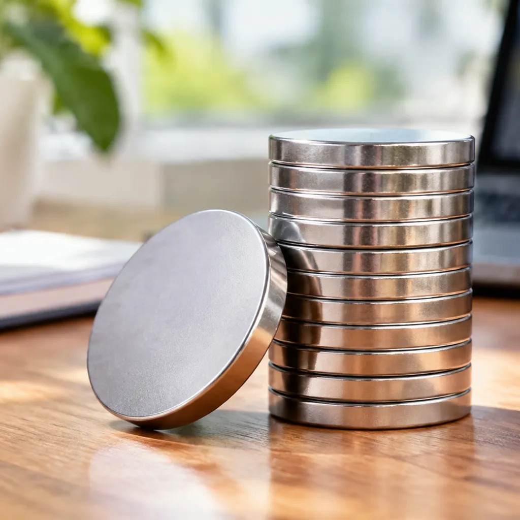
Fàg Beachd